INSTALLATION AND SERVICE INSTRUCTION
Siemens Industry, Inc.
UM91-HF
Rev 6
July 2012
Supersedes Rev 5
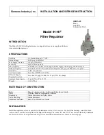
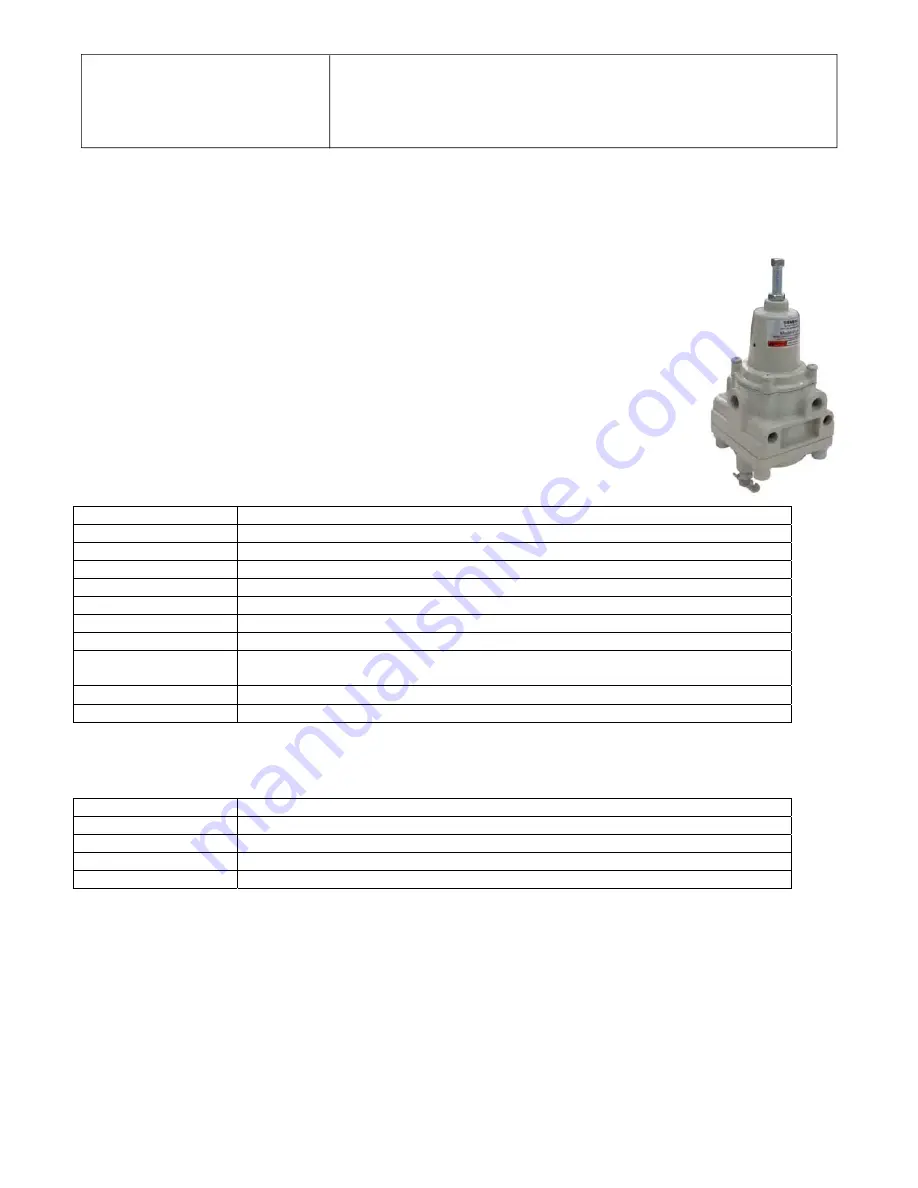
Model 91-HF
Filter Regulator
INTRODUCTION
The Model 91-HF Filter Regulator removes impurities from an air supply and delivers
an accurate output pressure.
SPECIFICATIONS
Port Size
(In, Out and Gauge) ¼" NPT
Output Range
0-120 psig (0-800 kPa)
Max Supply Pressure
150 psig (1034 kPa)
Mounting
Pipe or Through Body
Flow Capacity
22 SCFM (33.0 m
3
/hr) at 100 psig (700 kPa) supply with 20 psig (140 kPa) output
Exhaust Capacity
0.1 SCFM (0.17 m
3
/hr) with downstream pressure 5 psig (35 kPa) above set point
Sensitivity
1" (2.5 cm) of water
Air Consumption
Less than 5 SCFM (0.17 m
3
/hr)
Effect of Supply
Pressure Variation
Less than 0.2 psig (1.4 kPa) for 25 psi (170 kPa) change
Ambient Temp Limits
0° to 160
°
F (-18° to 71
°
C)
Weight
1.6 lb (725 g)
MATERIALS OF CONSTRUCTION
Body
Diecast Aluminum Alloy, Irridite and Baked Epoxy Finish
Filter
3 Micron Phenolic Impregnated Cellulose
Diaphragm
Nitrile Elastomer and Nylon Fabric
Valve Seat Plug
Nitrile Elastomer
Additional Materials
Brass, Zinc Plated Steel, Acetal
INSTALLATION
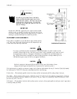
Install the regulator as close as possible to the instrument or tool it is to service. For best filter drainage, orient the drain
valve so that it is at the lowest point on the drip-well housing. The words “IN” and “OUT” are cast into the body to indicate
the direction of flow. See Specifications for port size. Installation dimensions are shown on the next page.

