DESCRIPTION
1-12
Document No.: COM-00-05-16 June 2006, Revised June 2014
Version: C.1
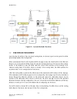
In addition to other typical configuration requirements for the WAG, in general, the following are
required for OSI to work:
1.
The Type 3 ATCS address option must be configured with a proper address.
2.
The WAG Circuit ID must be configured.
3.
One or both of the Routing Region Domains must be configured with valid IP addresses or
symbolic names.
4.
The ATCS UDP Server Port Number must be configured with a valid port number.
1.7
BOOT LOADER RS485 J1/J2 JUMPER DETECTION
If the WAG is configured for RS485 Half-Duplex serial interface operation and if RS485 J1/J2
Jumper Detect is ENABLED (described below), then the Boot Monitor will perform automatic J1/J2
jumper detection.
On the WAG hardware there are two jumpers which are shipped from the factory as un-jumpered.
These jumpers are used to connect the serial interface’s Transmit and Receive signals together.
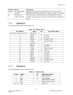
On the serial interface when J1/J2 are in place, pins 2 and 3 on J1 (transmit and receive) are tied
together to form half of the balanced wire signaling. Pins 14 and 16 on J1 (secondary transmit
data and secondary receive data) are tied together to form the second half of the balance wire
signal.
The WAG’s Boot Monitor can detect the presence of these jumpers by transmitting a test frame in
RS232 mode and see if it loops back to its receiver. If the test frame is looped back, it means that
the jumpers are in place.
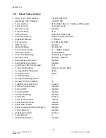
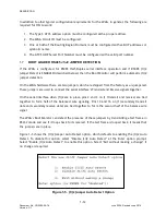
Figure 1-5 shows the J1/J2 Jumper Auto Detect option, which defaults to enabling the J1/J2 Auto
Detect. To disable this option, select “Disable J1/J2 Auto Detect” at the Enter option prompt.
Select “Enable J1/J2 Auto Detect” to enable this option. Select “Exit without making a change” if
no change is required.
Figure 1-5.
J1/J2 Jumper Auto Detect Option


