background image

3

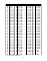
4. Find the correct setting for the ACM-1

address in Table 1 on page 6 of these
instructions and use dipswitch S102,
switches SW1 through SW8, to set the
address for the module.

NOTE: To open a dipswitch,

 press

down on the side of the
dipswitch marked OPEN. To
close a dipswitch, press down
on the side of the dipswitch
opposite the side marked
OPEN.

To


open a slide switch,

 push

the slide to the side opposite
the side marked ON. To close a
slide switch, push the slide to
the side marked ON.

To mount the ACM-1 module:

The ACM-1 may be mounted in two differ-
ent locations in the enclosure, depending on
whether or not there is an MKB-2 in the
enclosure. (In some cases an MHD-3 is
used instead of the MKB to enable the use
of more VSMs in a system.)

1. When an MKB-2 is in the top

position of the system enclosure:

a. Mount the ACM-1 module on the

back of the MKB-2 front panel,
below the ANN-1 module. Check
that the ribbon cable connector P1 is
in the upper left corner of the board
before mounting.

b. With the board in that position, place

the module over the five threaded
mounting spacers. (See Figure 2.)

c. Fasten the module in place with the

No. 6 screws provided.

2. When an MHD-3 is used in the top

position of the enclosure (instead of
an MKB-2):

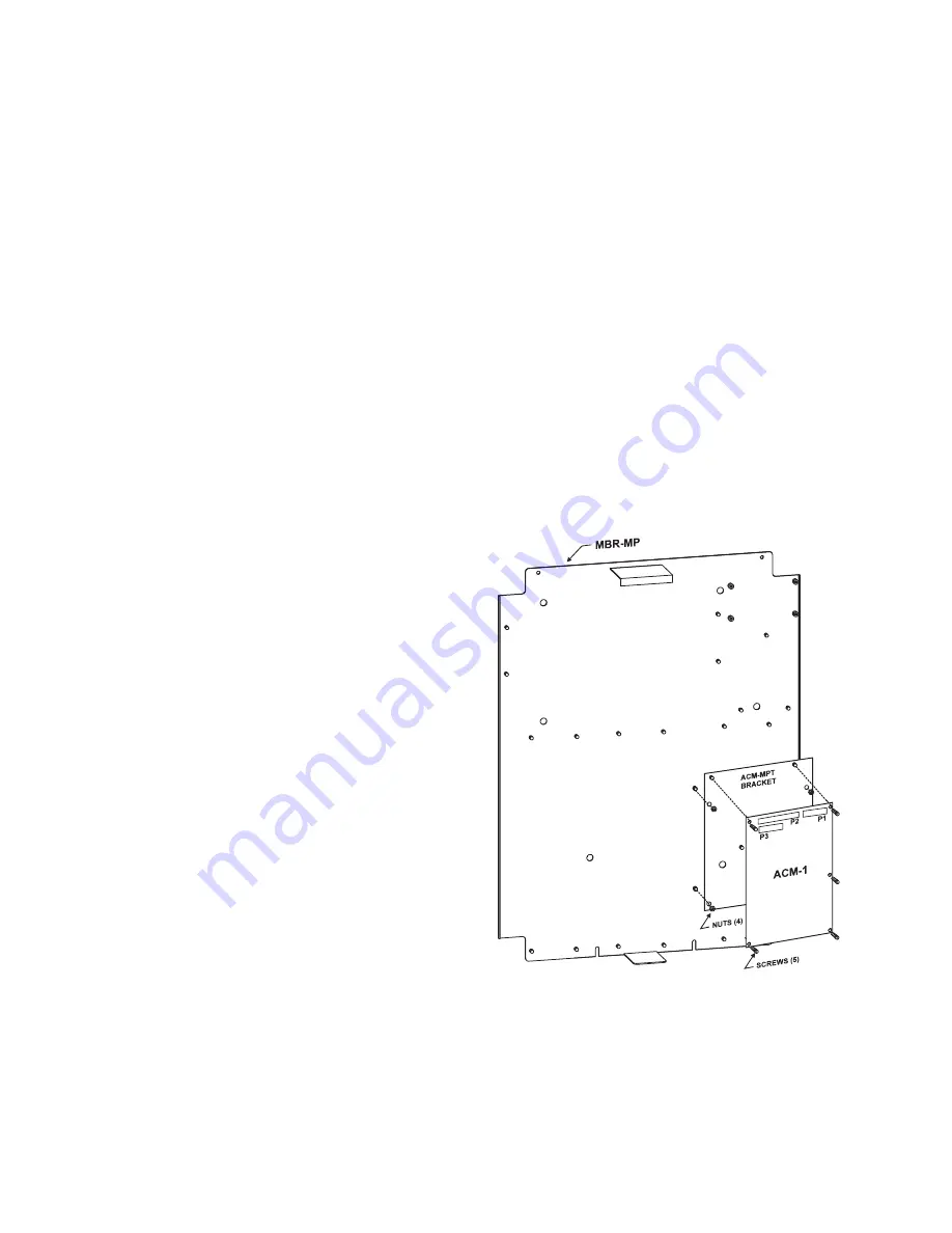
a. Mount the ACM-MPT bracket on the

4 studs located in the lower right
hand corner of the MME-3 backbox.
(These are the same studs used for
a TSP-40 printer.) Secure the
bracket with the four nuts provided.
(See Figure 3.)

b. Be sure that P1 is in the upper right

hand corner of the ACM. (Refer to
Figure 3.) Mount the ACM-1 PC
board over the six threaded mount-
ing spacers.

c. Fasten the module in place with the

five No. 6 screws provided (one of
the spacers is used for support).
(Refer to Figure 3.)

Figure 3

Alternate Mounting of ACM-1

Summary of Contents for ACM-1

Page 1: ...e set with CSG M If an application requires tone backup use the P6 connector on the ACM 1 for the BTC 1 Backup Tone card Refer to Figure 1 The ACM 1 occupies one network address The switch S102 shown in Figure 2 is used to set the network address that was chosen in CSG M for the ACM 1 module OPERATIONS 1 The ACM 1 controls and supervises the preamplifier circuit for the microphone and wiring for t...

Page 2: ...available in the System can be sent to this speaker if selected in CSG M 4 Three supervised riser circuits provide low power audio signals to the OCC 1 to be sent to power amplifiers The ACM 1 can also connect these risers to an auxiliary non emergency signal source for use in non emergency audio applications 5 The Audio Control module communi cates with the VSM 1 Voice Switch modules the VLM 1 Vo...

Page 3: ...ion of the system enclosure a Mount the ACM 1 module on the back of the MKB 2 front panel below the ANN 1 module Check that the ribbon cable connector P1 is in the upper left corner of the board before mounting b With the board in that position place the module over the five threaded mounting spacers See Figure 2 c Fasten the module in place with the No 6 screws provided 2 When an MHD 3 is used in...

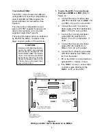
Page 4: ...r by color tracers on the wires In Nos 1 and 2 below be sure the black tracer wire is close to the 1 1 To wire the ACM 1 in an enclosure that has an MMB or a PSR Refer to Figure 4 a Connect the long 15 ribbon cable P N 555 192238 from the MMB P8 or PSR 1 P5 to P5 on the ACM 1 b Connect the short 15 conductor ribbon cable P N 555 192242 from ANN 1 P3 to P4 on the ACM 1 c Connect the 14 conductor ri...

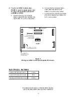
Page 5: ...e ACM 1 b Connect the 50 conductor ribbon cable P N 555 192201 from TBM 2 P3 to P2 on the ACM 1 c Connect the 5 conductor wire cable P N 600 190220 from TBM 2 P2 to P3 on the ACM 1 For additional information on the MXL MXLV System refer to the MXL MXLV Manual P N 315 092036 ELECTRICAL RATINGS t n e r r u C e l u d o M C D V 5 e v i t c A A m 6 7 1 t n e r r u C e l u d o M C D V 4 2 e v i t c A A ...

Page 6: ...XOXXX 131 132 133 134 135 136 137 138 139 140 141 142 143 144 145 146 147 148 149 150 151 152 153 154 155 156 157 158 159 160 161 162 163 164 165 166 167 168 169 170 171 172 173 174 175 176 177 178 179 180 181 182 183 XOOOOOXX XOOOOXOO XOOOOXOX XOOOOXXO XOOOOXXX XOOOXOOO XOOOXOOX XOOOXOXO XOOOXOXX XOOOXXOO XOOOXXOX XOOOXXXO XOOOXXXX XOOXOOOO XOOXOOOX XOOXOOXO XOOXOOXX XOOXOXOO XOOXOXOX XOOXOXXO XO...

Page 7: ...7 ...

Page 8: ...Siemens Industry Inc Building Technologies Division Florham Park NJ Siemens Building Technologies Ltd Fire Safety Security Products 2 Kenview Boulevard Brampton Ontario L6T 5E4 Canada P N315 092083 10 ...

Reviews: