background image

5/10

Siemens Building Technologies

Fan coil controller for wall mounting ACR12

CE1N3573E

HVAC Products

17.08.2001

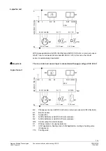
With 10 % control of the heating or cooling valve, the fan switches to speed I, with 80 %
to speed II and with 100 % to speed III. The switching hystereses of the fan speeds are
shown in the following  diagram.

Q1

Q2

Q3

0

10

50

80

100

0

10

50

80

100

35

73

D

06

Q


[%]

Q

H


[%]

W

H

W

K

X

p

X

p

X

dz

Ventilation in the neutral zone OFF. Mode 1, i.e. S8 = on

When an energy requirement of 10 % is reached, the fan switches to speed 1
(S8 = on), if the position “Auto” automatic operation is selected.
During dead zone is a periodical fan operation active, which is starting the fan every 30
min. for 1 min.

W

H

W

K

X

p

X

p

X

dz

Q1

Q2

Q3

50

80

100

50

80

100

35

73

D

07

Q

K


[%]

Q

H


[%]

Ventilation in the neutral zone ON. Mode 2, i.e. S8 = off

The user can select a fan speed dwell time of 1 or 2 minutes. This applies for automatic
operation and can be set with switch S4.

 Q1

 Fan speed 1

 W

H

 Heating setpoint

 Q2

 Fan speed 2

 W

K

 Cooling setpoint

 Q3

 Fan speed 3

 X

p

 P-band

 Q

H

 Heating load

 X

dz

 Neutral zone

 Q

K

 Cooling load


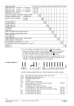
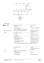
Settings on the device

Various settings can be made on the printed circuit board of the device using a 12 way
DIP switch (see the following diagram). For changes to take effect, the device must be
disconnected from the power supply.

Summary of Contents for ACR12.3 0 Series

Page 1: ...H11 Potential free input for window contact or occupancy detector Inbuilt room temperature sensor Three operating modes Comfort Economy Standby The status of the operating mode switch è è è è and changeover switch are memorised on power failure Use For controlling the room temperature in individual rooms and zones which are heated and cooled by fan coils The controllers are suitable for 2 or 4 pip...

Page 2: ...ccording to the resulting deviation the processor calculates the pulse dura tion ratio for control of the thermic valve actuators and if necessary for the electric heater At the same time the optimum fan speed is automatically selected if the fan speed selector switch on the controller is set to Auto The user can choose between P proportional and PI proportional integral control These and other se...

Page 3: ... ALG ACR12 340 ALG and ACR12 321 ALG ACR12 341 ALG QH Heating load WH Heating setpoint QK Cooling load WK Cooling setpoint Xp P band XPE P band electric heater Y Positioning variable YH Heating output with ACR12 32x ALG ACR12 34x ALG c o activated YHE Electric heater output with ACR12 32x ALG YK Cooling output with ACR12 32x ALG ACR12 34x ALG c o deactivated Control sequence 4 pipe fan coil Contro...

Page 4: ...g operation takes place manually on the device If a C O sensor type QAH11 is connected or terminals B2 M are getting bridged by means of an external switch changeover is automatic The controller de tects a C O sensor automatically In this case the manual C O switch is deactivated Above the entry key of the changeover sensor the types ACR12 320 and 340 are indi cating with LED s the operation of he...

Page 5: ...atic operation is selected During dead zone is a periodical fan operation active which is starting the fan every 30 min for 1 min WH WK Xp Xp Xdz Q1 Q2 Q3 50 80 100 50 80 100 3573D07 QK QH Ventilation in the neutral zone ON Mode 2 i e S8 off The user can select a fan speed dwell time of 1 or 2 minutes This applies for automatic operation and can be set with switch S4 Q1 Fan speed 1 WH Heating setp...

Page 6: ... and in bold print in the above table on Change of the operating mode can be made with the button on the controller by means of a window contact occupancy detector or otherwise terminals DU1 GND Input DU1 GND has a higher priority than the button In case the controller is in operating mode marked the setpoint shift of 6 K is not active If any operation is carried out on the front of the controller...

Page 7: ...d The c o or return air sensor input is connected with supply voltage of AC 230 V B2 Changeover sensor ACR12 32x ALG or return air sensor ACR12 34x ALG E1 Electric heater M1 3 speed fan N1 ACR12 340 ALG or ACR12 341 ALG controller N2 ACR12 320 ALG or ACR12 321 ALG controller Q14 Control output for electric heater S1 Window contact occupancy detector Y1 In N1 application heating valve In N2 applica...

Page 8: ...stallation Instructions G3573X The controller is not approved for mounting on metallic surfaces unless the sur face is permanently connected to a protective conductor Safety instructions The controller must be installed by the customer according to the safety regula tions VDE 0700 EN 60 335 2 73 If the safety device is activated the installation must be thoroughly checked before the system is rese...

Page 9: ... Fan control Q1 Q2 Q3 AC 230 V Q1 load max 230 VA cos ϕ 0 9 Q2 Q3 load max 450 VA cos ϕ 0 9 Electric heater Q14 AC 230 V Load max purely resistive 2850 VA AC 230 V 12 5 A Contact life B10 100 000 switching cycles Load reduced purely resistive 1250 VA AC 230 V 5 5 A Contact life B10 300 000 switching cycles B10 number of switching cycles reached by at least 90 of the relays Valve control Y1 Y10 AC ...

Page 10: ...midity 85 rH Transport Class 2K3 to IEC 721 Temperature 25 65 C Humidity 95 rH Conformity according to EMV directive 89 336 EWG Low voltage directive 73 23 EWG Electromagnetic compatibility Immunity to interference EN 50082 1 Emissions EN 50081 1 Product safety Automatic control devices for use in the home and similar applications EN 60730 1 Special requirements for energy controllers EN60730 2 11...

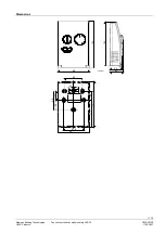
Page 11: ...11 10 Siemens Building Technologies Fan coil controller for wall mounting ACR12 CE1N3573E HVAC Products 17 08 2001 Dimensions 98 143 135 44 39 56 4 1 58 28 61 6 7 4 85 5 30 98 2 2 28 143 3573M01 ...

Page 12: ...12 10 Siemens Building Technologies Fan coil controller for wall mounting ACR12 CE1N3573E HVAC Products 17 08 2001 ã1999 Siemens Building Technologies Ltd Subject to change ...

Reviews: