7 / 14
Siemens
Electromotive actuators for combi valves
CE1N4833en
Building Technologies
2017-11-15
4833Z15
1
2
3
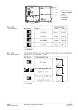
1
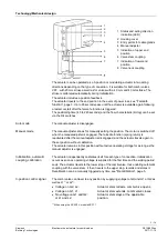
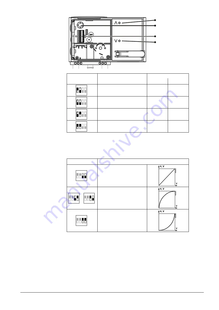
1 Status and acting
direction indication
(LED)
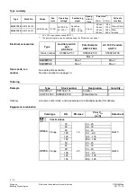
2 DIL switch
3 Connection
terminals
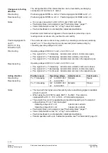
DIL switch
Speed
Positioning time
1)
20 mm
40 mm
1 2 3 4
ON
48
3
3Z
0
2a
2 sec/mm
40 sec
2)
80
sec
2)
1 2 3 4
ON
48
3
3Z
0
2b
3 sec/mm
60 sec
120 sec
1 2 3 4
ON
48
3
3Z
0
2c
4,5 sec/mm
90 sec
180 sec
1 2 3 4
ON
48
3
3Z
0
2d
6 sec/mm
120 sec
240 sec
1)
Tolerance: ± 1 sec
2)
Factory setting
The flow characteristics can be used only for connections with constant positioning
signals DC 0…10 V and DC 4…20 mA.
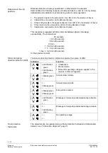
DIL switch
Flow characteristics
1 2 3 4
ON
48
3
3Z
0
3a
lin = linear
1)
1 2 3 4
ON
48
3
3Z
0
3b
1 2 3 4
ON
48
3
3Z
0
3c
log = equal percentage, n
gl
=
3
(logarithmic normal)
1 2 3 4
ON
48
3
3Z
0
3d
log = equal percentage, n
gl
=
3
(exponential normal)
1)
Factory setting
Positioning times
DIL switch
DIL switch
Flow characteristics


