Siemens Industry, Inc.
Building Technologies Division
9
P/N 315-049708-5
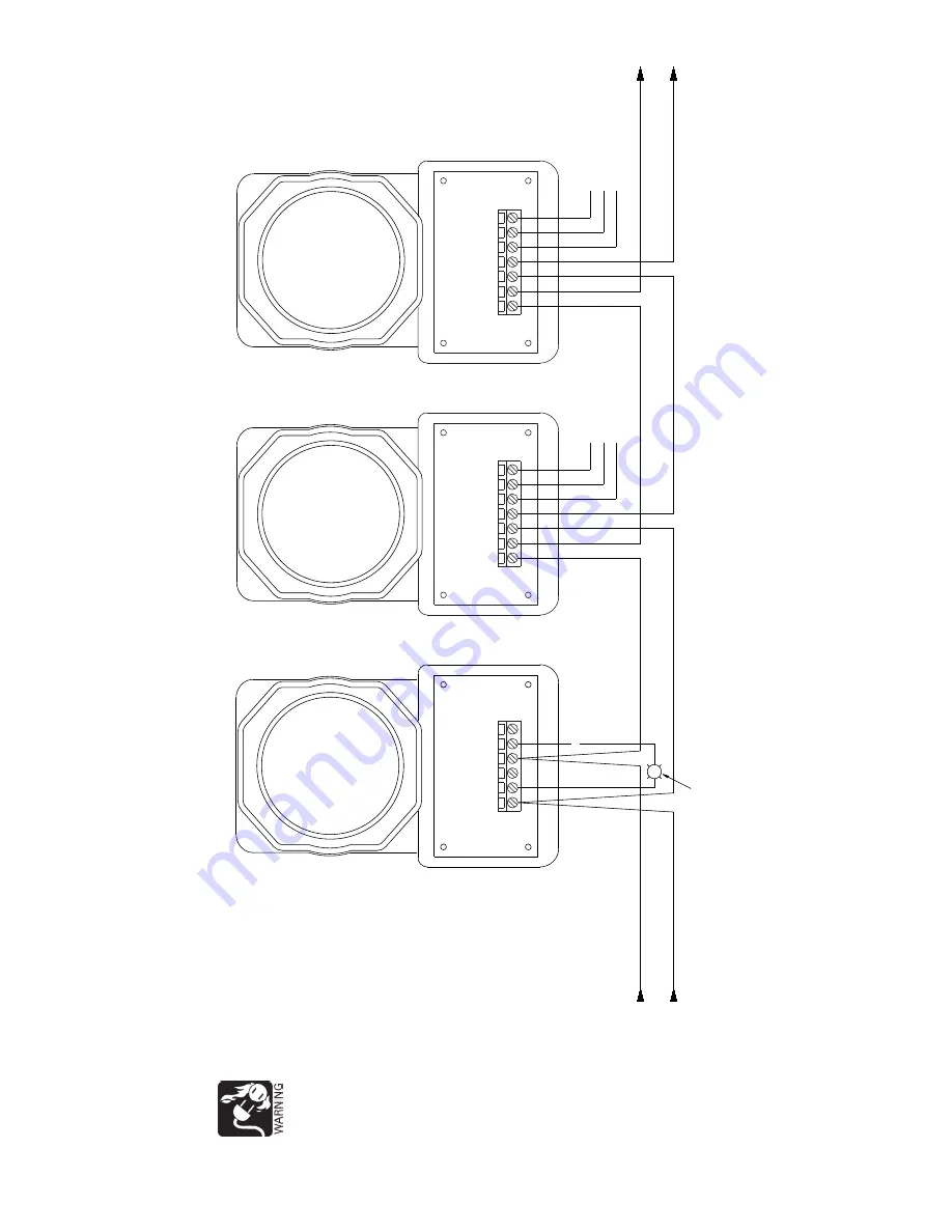
Figur
e 6
Typical Connections f
or
the
AD2-P /
AD2-XHR Using FP
-1
1 / FP
-1
1C Detector
s
N
O
TES:
1.
The rela
y cont
acts are sho
wn af
ter
a r
eset pulse,
whic
h repr
esents the non-alarm condition.
2.
The gr
een grounding scr
ew
in the wiring compar
tment of the air
duct housing is not used.
-
+
DEVICE LOOP
-
DEVICE LOOP
+
NOT USED
OPTIONAL
REMOTE
ALARM
INDICA
T
O
R
M
ODEL
RLI-1
OR
RLI-2
RED
REMOTE
-
REMOTE
+
NO
LOOP
DEVICE
++
-
-
NC
COM
NO
ALARM
RELA
Y
COM
NC
COM
NC
NO
T
O
NEXT
ADDRESSABLE
DEVICE
-
+
TB1
TB1
TB1
MODEL
AD2-P
MODEL
AD2-XHR
MODEL
AD2-XHR
FP-1
1
FP-1
1
C
LOOP
WIRES.
SEE
COMP
A
TIBLE
CONTROL
EQUIPMENT
T
ABLE.
FP-1
1
FP-1
1C
FP-1
1
FP-1
1C
ALARM
CONT
ACTS
125
V
AC,
24
VDC,
2.5A
SEE
NOTE
1
ALARM
CONT
A
CTS
125
V
A
C,
24
VDC,
2.5A
SEE
N
OTE
1
NO
LOOP
DEVICE
++
-
-
ALARM
RELA
Y
COM
NC
NOT USED
If the r
ela
y cont
acts
ar
e being used to
contr
ol 1
20
VA
C
oper
ated eq
uipment,
ensur
e that the
conduit is pr
operly
at
ta
ched to the
internal metal
gr
ound str
ap,
using
the pr
oper
conduit
loc
king nuts.
F
ailur
e
to
pr
o
vide pr
oper
g
rounding ma
y
result in f
atal
electrical shoc
k
and violation of
national and local
codes.


