7SG11 Argus 8 Description of Operation
sequence calculations. The ZPS calculation, which is used in the neutral voltage displacement (NVD) function
also benefits from excellent inherent 3
rd
harmonic rejection.
All relays are fully calibrated during manufacture using accurate voltage source equipment. Calibration
coefficients are stored in EEPROM and are used by the processor to compensate for any inaccuracies in the
input stage, which have been introduced by the analogue circuits. Errors in magnitude and phase are eliminated
using this method.
3
Protection Functions
3.1
Voltage Blocking Element
The voltage blocking element acts as a block to the Voltage, Frequency and NPS elements in the relay. If all
phase voltages fall below the threshold level then the blocking operation will operate. This block does not apply to
the NVD elements.
•
For 3 pole relay variants: Voltage blocking is applied when all 3 phases fall below the threshold level.
(If set to 2Ph-Ph+NVD, then when the two phases fall below).
•
For 2 pole relay variants (set as 2Ph-Ph): Voltage blocking is applied when both phases fall below the
threshold level.
The setting range for the voltage blocking threshold is OFF, 1V - 100V with a 1V step . This element is required
mainly for undervoltage operation conditions. Under normal circumstances, if all phase voltages fall below the
undervoltage setting, a trip output would be the expected response. However, in some applications e.g. auto-
reclose schemes, having an undervoltage relay trip when the line is de-energised during the auto-reclose
sequence is not usually desirable. Blocking the undervoltage operation in this situation can be achieved by using
the Voltage Blocking Threshold, which should generally be set above the level of expected induced voltages on
the line.
(See Applications Guide Section 2.2 for more information regarding this element).
3.2
Voltage Elements
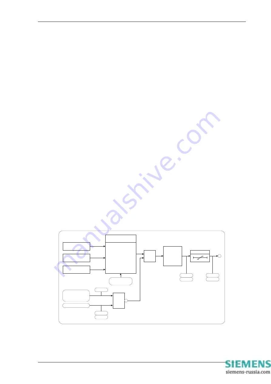
Each version of the Argus 8 relay has 4 voltage elements as standard. These can be configured to be either
undervoltage (U/V) or overvoltage (O/V) elements. If the input voltages exceed the pickup level, whether U/V or
O/V, then each element operates through a gate, which selects operation from any one phase or all phases. At
this point the element can still be inhibited from starting, using either a status input inhibit or if the input voltages
are below the voltage blocking threshold level. Figure 1 shows the basic operation of each voltage element. The
‘event’ and ‘instrument’ labels in the diagram indicate where this type of information is generated.
V
A
Pickup Value
V
B
Pickup Value
V
C
Pickup Value
Any 1
or
All
V Element O/P Phases
Setting Select
&
1
Status Input
(VA & VB & VC)
☯
V Block Threshold
V Element
Starter
DTL
Event
Instrument
Event
Trip
Instrument
Event
Instrument
Event
(V Element Inhibit)
Block
Figure 1 - Voltage Element
The voltage elements each have a variable hysteresis setting which allows the user to vary the pick-up - drop-off
ratio for a particular element.
©2010 Siemens Protection Devices Limited
Chapter 1 Page 8 of 20


