7SG11 Argus 8 Commissioning
Status 8
39
40
Status 9
37
38
Record the operation of the Status Inputs in Table 1.
3.9 Output Relay Tests
This test checks that the output relays are functioning correctly. The output relays should be energised
in turn and the contacts should be checked for correct operation using a continuity tester. The output
relays can be energised in a number of ways. The following is the recommended method :
Assign each output relay in turn to ‘Protection Healthy’ in the output relay menu. On pressing the
ENTER
key the output relay selected will be energised. Check with a continuity tester that the actual
contacts have operated. De-select the output relay and check that the contact returns.
(Assigning the output relays to ‘Protection Healthy’ ensures that they stay energised until they are de-
selected. Otherwise, if they were assigned to a protection element, they may only be energised for the
minimum output contact time, which is 100ms. This might not be long enough time for a continuity
tester to register.)
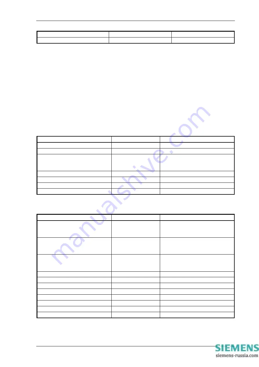
Connect the continuity tester between the following terminals to test the output relays :
For E4 case size relays :
Output Relay
Type
Terminal No.
Relay 1
N/C
7 – 8
Relay 2
N/O
9 – 10
Relay 3
C/O
17 (COM)
18 (N/C)
16 (N/O)
Relay 4
N/O
11 – 12
Relay 5
N/O
19 – 20
Relay 6
N/O
21 – 22
Relay 7
N/O
23 – 24
For E6 case size relays :
Output Relay
Type
Terminal No.
Relay 1
C/O
6 (COM)
5 (N/C)
7 (N/O)
Relay 2
C/O
9 (COM)
10 (N/C)
8 (N/O)
Relay 3
C/O
17 (COM)
18 (N/C)
16 (N/O)
Relay 4
N/O
11 – 12
Relay 5
N/O
19 – 20
Relay 6
N/O
21 – 22
Relay 7
N/O
23 – 24
Relay 8
N/O
37 – 38
Relay 9
N/O
39 – 40
Relay 10
N/O
41 – 42
Relay 11
N/O
43 – 44
©2010 Siemens Protection Devices Limited
Chapter 7 Page 6 of 12


