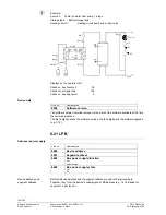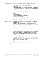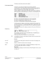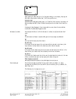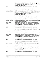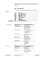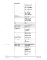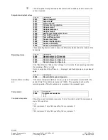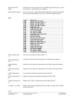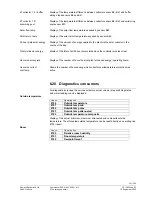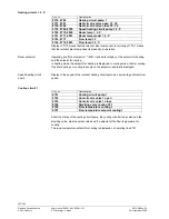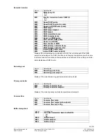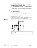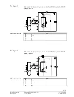
Input test H1, H2, H3
Line no.
Operating line
7840
Voltage signal H1
7841
Contact state H1
Open.
Closed).
7842
Pulse counter H1
7845
Voltage signal H2
7846
Contact state H2
Open.
Closed).
7854
Voltage signal H3
7855
Contact state H3
Open.
Closed).
7856
Pulse counter H3
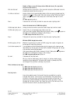
Shows the value of the pending voltage signal (DC 0…10 V).
Voltage signal
H1, H2, H3
Shows the current state of contact H1.
Contact state
H1, H2, H3
Each recorded pulse is counter in a free, unitless
pulse counter Hx
if the Hx input is
configured as the pulse counter.
Pulse counter
The counter difference is read from this pulse counter periodically (1 minute) and the
energy increase of volume flow is calculated.
The pulse counter is not stored during a power outage. The pulses are lost during a
reading period.
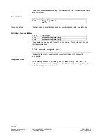
The pulse counter is visible in the
Input / output test
menu.
The pulse counter is displayed with the value "---" if the Hx input is not configured as
the pulse counter.
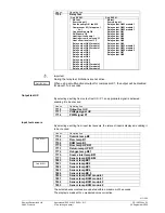
Input test E
Line no.
Operating line
7889
Low-pressure switch E9
0 V
230 V
7890
High-pressure switch E10
0 V
230 V
7891
Compressor 1 overload E11
7911
Input EX 1
7912
Input EX 2
7913
Input EX 3
7914
Input EX 4
7915
Input EX 5
7916
Input EX 6
7917
Input EX 7
Only RVS61..
By selecting a setting from input test E, the relevant input will be displayed, enabling
checking.
212/258
Siemens Switzerland Ltd
User manual RVS61.843, RVS41.813
CE1U2355en_02
HVAC Products
6 The settings in detail
28. September 2009

