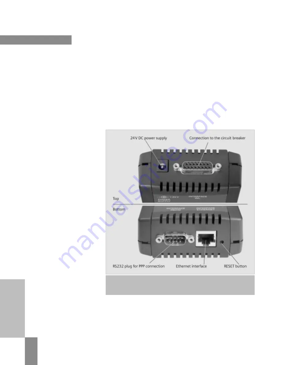
To operate the BDA, it must be
connected to the target system
(e.g. a PC) on one side and a
circuit breaker on the other.
Different scenarios are possible
depending on the application.
For WL Circuit Breakers, two basic
methods are available for connecting
the BDA; temporary or permanent
installation.
Temporary
If the BDA is to be used as a local
parameterization tool and several
circuit breakers are to be set in
succession, the local front interface
of the trip unit can be used. The
cable required is supplied with the
BDA. An additional 24V DC power
supply unit is also required if the
circuit breaker is not yet supplied
with power via the
Cubicle
BUS
. For
this purpose, a voltage connection
is located on the top of the BDA next
to the interface to the circuit breaker.
In temporary mode, the BDA can be
quickly secured to any switchgear
cubicle using magnets on the back.
Note:
Do not use temporary magnetic
installation for BDA where it can fall
into energized parts.
Permanent
The trip unit interface through the
front connection is not suitable if a
BDA or BDA
Plus
is to be permanently
connected to a WL Circuit Breaker.
The connection on the last
Cubicle
BUS
module, such as the COM15 module,
or one of the other modules, is
more suitable. In this case, a cable
is supplied with the BDA that can
be connected directly to the RJ45
plug-in contact of the
Cubicle
BUS
module. Typically, a BDA
Plus
is
used for permanent installation.
The DIN rail installation kit supplied
is used to secure the device.
The principle regarding the power
supply is the same as for temporary
operation: if the
Cubicle
BUS
is
supplied with power, the BDA will
also operate without an extra power
supply unit. Otherwise, the BDA must
also be connected to a 24V DC power
supply unit.
Breaker Data Adapter (BDA)
Connection to WL Circuit Breakers
4/5
WL Circuit Breaker
Figure 4-1
The physical BDA interfaces. The connection to the circuit breaker and optional power
supply are on the top, while the RS232 interface (or the Ethernet interface in the case of BDA Plus)
and the RESET button are on the bottom.
WL PROFIBUS Communication and Electronic Accessories • July 2004


