Table 4-1
The LEDs on the BDA indicate the
current operating status.
Operation
As a microcomputer, the BDA is
booted in the same way as a PC.
This takes approximately 40 seconds
and is started automatically when
the power supply is switched on.
During this time, the content is
loaded from the Flash memory to
the main memory, an internal self
test is carried out, the operating
system (embedded Linux) is booted,
and the web server application
started.
The RESET button on the underside
enables the BDA to be restarted
manually at any time.
The LEDs indicate the operating
status during the boot-up process.
The upper DEVICE LED is first
red/green, while the lower
Cubicle
BUS
LED is red only. After
about 10 seconds, this also changes
to red/green. During the load
process, the Ethernet connection is
checked for a connected network.
Only then is the appropriate driver
loaded. Since the BDA Plus is to
be operated with an Ethernet
connection, a physical connection
to the Ethernet must already exist
during the boot-up process.
4/6
Meaning of the LEDs on the BDA
LED
DEVICE
Cubicle
BUS
Meaning
BDA out of order
BDA in operation
BDA booting up
BDA in online
mode and
connection to
circuit breaker
interrupted
Connection
exists to
Cubicle
BUS
BDA booting up
BDA in offline
mode, even if
circuit breaker
is connected
Display
red
green
red/
green
red
green
red/
green
off
Breaker Data Adapter (BDA)
WL Circuit Breaker
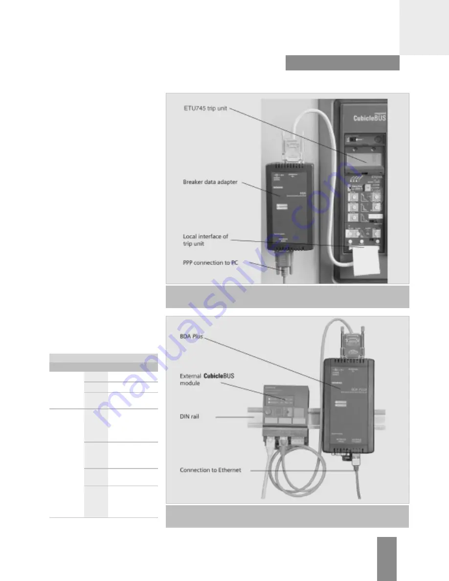
Figure 4-2
For temporary operation, the BDA can be connected to the local interface of the trip unit.
In this configuration, only the RS232 connection to the PC is typically used.
Figure 4-3
In a permanent installation, the BDA should be connected to the last external
Cubicle
BUS
module. It can be secured using a DIN rail, as shown above.
WL PROFIBUS Communication and Electronic Accessories • July 2004


