background image


Instruction manual AQ101, AQ101D, AQ110P, AQ01 

   42 (48

)


8.2


AQ01

 ARC FLASH SENSOR


Figure 8-6: AQ01 sensor dimensions, all dimensions in millimeters. 


Summary of Contents for Arcteq AQ01

Page 1: ...INSTRUCTION MANUAL AQ101 AQ101D AQ110P AQ01 ...

Page 2: ... 48 Revision History Revision Public EN_MV_1 0 Date 15 May 2020 Changes N A Revision Public EN_MV_1 1 Date 09 June 2020 Changes Scheme 2a tripping matrix table is added Scheme 2a dipswitch setting is added Application example of scheme 2a is added ...

Page 3: ...reviations HSO High speed output BI Binary input BO Binary output CBFP Circuit breaker failure protection QD Quenching device IL Phase current Io Neutral sequence current LED Light emitting diode L Light signal I Overcurrent signal MT Master trip signal ...

Page 4: ...Potentiometers AQ110P only 16 2 3 Siemens Protection Scheme logics AQ101 AQ101D AQ110P 16 2 3 1 AQ101 AQ101D 17 2 3 2 AQ110P 17 2 3 3 I O Description 19 3 OPERATION 20 3 1 AQ101 AQ101D AQ110P arc flash protection relays 20 3 1 1 LED indicators 20 3 1 2 Text pocket 22 3 1 3 Set button 23 3 2 AQ01 arc flash sensor 24 4 COMMISSIONING 25 4 1 AQ101 AQ101D AQ110P arc flash protection relays 25 4 1 1 Sys...

Page 5: ... 1 4 Current measurement circuits IL1 IL3 Io AQ110P only 34 7 1 5 Trip relays T1 T2 T3 T4 34 7 1 6 High Speed Outputs HSO1 HSO2 AQ110P only 35 7 1 7 Binary Output BO1 35 7 1 8 Binary Inputs BI1 BI2 35 7 2 AQ01 arc flash sensor 36 8 DIMENSIONS 37 8 1 AQ101 AQ101D AQ110P arc flash protection relays 37 8 2 AQ01 arc flash sensor 42 9 ORDERING CODES 43 9 1 AQ101 AQ101D AQ110P Arc Flash protection relay...

Page 6: ...N OFF SW1 ON OFF MadeinFinlan d AQY004d 1A 5A IL1 IL2 IL3 HSO1 HSO2 Io 1A 5A 1 A 5 A 1A 5A S3 24Vdc de energized position 15 14 13 12 11 10 8 7 6 5 4 9 3 2 1 S S S S X3 X2 X1 12 11 10 9 8 7 6 5 4 3 2 1 BI2 24 72V dc 80 265Vac dc BI1 T1 T2 T3 T4 15 14 13 12 11 10 8 7 6 5 4 9 3 2 1 SF Uaux www ar cteq fi GND 0 5 0 05 1 0 6 0 RX S5 Io set I set xIn S4 BO1 S1 S2 X 3 X 2 X 1 T1 T2 L atc h no nLat ch H ...

Page 7: ...2 AQ101D ARC FLASH PROTECTION RELAYS Figure 1 2 AQ101D din rail mounting Installation picture See panel cut out dimensions on separate cut out sheet included with this manual See installation and mounting related technical parameters refer to chapter 8 1 ...

Page 8: ...Instruction manual AQ101 AQ101D AQ110P AQ01 8 48 1 1 3 AQ01 ARC FLASH SENSOR Figure 1 3 AQ01 Installation picture See installation and mounting related technical instructions in chapter 8 2 ...

Page 9: ...al Self supervision contact failure state Sensor Channel 3 and 4 Grounding Self supervision contact common Sensor Channel 4 Supply Power supply positive Sensor Channel 4 Signal Power supply negative X3 S5 Function Function Sensor 5 Receiver Current measurement input L1 Sensor 5 Transmitter Current measurement input L1 Current measurement input L2 Current measurement input L2 Current measurement in...

Page 10: ...ntact T2 Sensor Channel 1 Grounding Trip contact T3 Sensor Channel 2 Supply Trip contact T3 Sensor Channel 2 Signal Trip contact T4 Sensor Channel 2 Grounding Trip contact T4 Sensor Channel 3 Supply Self supervision contact normal state Sensor Channel 3 Signal Self supervision contact failure state Sensor Channel 3 and 4 Grounding Self supervision contact common Sensor Channel 4 Supply Power suppl...

Page 11: ...tion manual AQ101 AQ101D AQ110P AQ01 11 48 1 2 3 AQ01 ARC FLASH SENSOR Function Sensor Grounding Sensor Signal Sensor Supply See rated voltages and connector tightening torques from chapter 7 2 Technical data ...

Page 12: ...th light only criterion Tripping with light and current criterion 7 S1 L L I Sensor 1 tripping with light only criterion Sensor 1 tripping with light and current criterion 6 Latch On Off Output relays latched Output relays not latched 5 100 150 ms Circuit breaker failure protection operating time 100 ms Circuit breaker failure protection operating time 150 ms 4 Scheme Select Weight factor 0 Weight...

Page 13: ...h non Latch Trip relays 1 and 2 latched Trip relays 1 and 2 not latched 7 HSO Latch non Latch High speed outputs latched High speed outputs not latched 6 S1 P L NA Sensor 1 connected with AQ01 light sensor 5 S5 Fib loop Elim Sensor 5 connected with fiber loop sensor Sensor 5 connected with quenching device control TX only 4 Fast CBFP Fast mode tripping without circuit breaker failure protection Ci...

Page 14: ...onnected with AQ01 light sensor 5 S5 Fib loop Elim Sensor 5 connected with fiber loop sensor Sensor 5 connected with quenching device control TX only 4 Fast CBFP Fast mode tripping without circuit breaker failure protection Circuit breaker failure protection activated 3 100 150 ms Circuit breaker protection delay setting 100 ms Circuit breaker protection delay setting 150 ms 2 I 1A 5A Phase curren...

Page 15: ...onnected with AQ01 light sensor 5 S5 Fib loop Elim Sensor 5 connected with fiber loop sensor Sensor 5 connected with quenching device control TX only 4 Fast CBFP Fast mode tripping without circuit breaker failure protection Circuit breaker failure protection activated 3 100 150 ms Circuit breaker protection delay setting 100 ms Circuit breaker protection delay setting 150 ms 2 I 1A 5A Phase curren...

Page 16: ...ty of scheme 0 AQ101 AQ101D scheme 1a 1b and 2a AQ110P Following tables doesn t segregate the light and light current mode trip settings In case light and current mode has been chosen with dip switches corresponding sensor activation requires simultaneous overcurrent injection For the CBFP operation refer to the relevant dipswitch settings Activation table letters X activation of output when signa...

Page 17: ...tings Refer to DIP switch configuration S5 is optional and may be used as fiber optic sensor input AQ101 and AQ101D Refer to the technical manual and ordering codes T3 and T4 are mainly for fault location identification 2 3 2 AQ110P Scheme 1a Scheme 1b T1 T2 T3 T4 BO1 HSO1 HSO2 QD T1 T2 T3 T4 BO1 HSO1 HSO2 QD S1 X X X X X X X X X X S2 X Y X X X X X Y X X X X S3 X Y X X X X X Y X X X X S4 X Y X X X...

Page 18: ... be used as fiber optic sensor input or quenching device control Refer to the technical manual and ordering codes T3 and T4 are mainly for fault location identification When DIP switch SW2 4 is set to FAST mode the trip relay T2 is activated without CBFP function When DIP switch SW2 4 is set to CBFP mode the CBFP function activates trip relay T2 if sensor channel S2 S3 S4 or L input BI1 BI2 is act...

Page 19: ...l to connected AQ101 units In normal operation it is used to synchronize all connected AQ101 units HSO2 Send MT signal to connected AQ101 units When it activates the connected AQ101 units activate T1 and T2 trip relays BO1 Send sensor channel S1 S2 S3 S4 and binary input BI2 L signal to connected AQ110P T1 Trip relay for incomer circuit breaker T2 Trip relay for incomer upstream circuit breaker T3...

Page 20: ...ismatch Protection partly operational T1 T3 T4 Red Normal status Trip relays T1 T3 T4 activated N A T2 T4 Red Normal status Trip relays T2 T4 activated N A S1 Amber Normal status Corresponding sensor channel activated Corresponding sensor channel have loose connection or system set up not performed S2 S3 S4 S5 Amber Normal status Corresponding sensor channel activated Corresponding sensor channel ...

Page 21: ...e connection or system set up not performed S5 AQ110P Amber Normal status Corresponding sensor or quenching device channel activated Corresponding sensor channel have loose connection or system set up not performed BI1 BI2 Amber Normal status Corresponding binary input activated Corresponding binary input have loose connection BO1 Amber Normal status Binary Output activated N A IL1 IL2 IL3 Amber N...

Page 22: ...10P AQ01 22 48 3 1 2 TEXT POCKET All devices contain a text pocket for entering sensor specific information Text pocket can be slide out and texts can be entered with a pen or with ready print paper or label Figure 3 1 Using text pocket ...

Page 23: ... sensor amount the system configuration Switch any DIP switch back and forth one time press the button for 3 seconds All connected inputs LED s lit steadily during installation Clear the alarm signals Press the button once Respective blinking led indicators turns off Check the number of installed sensors and unit connections Binary inputs Press the button 3 times within 2 seconds Corresponding con...

Page 24: ...s of the sensor for series connecting maximum three sensors in one line After connecting the sensor to relay the ERROR LED turns on and the appropriate sensor channel LED starts to blink Press and hold the SET button on the front panel for 3 seconds to run system auto configuration setting See configuration related technical instructions in chapter 3 1 3 ...

Page 25: ...djusted to the pick up setting value by 1 Injecting the current level of desired pick up value to IL1 and Io separately 2 Starting from maximum setting adjusting the potentiometer slowly down 3 Corresponding current measurement channel LED lights steadily when the activation with injected current has occurred IL1 IL3 measurement channels have a common adjustment potentiometer I set Therefore each ...

Page 26: ...r sensors 1 Applying light to the sensor 2 Corresponding light sensor channel LED lights steadily when light has been detected Use strong non LED light source for light channel activation Light sensors are available with different sensitivity levels Least sensitive sensors require stronger light source Refer to sensor ordering codes Activation longer than 3s will initiate self supervision error Re...

Page 27: ...ependent on the application scheme of each device Refer to chapter 2 3 for definition of scheme logics and related LED indicators in chapter Error Reference source not found Activation of outputs from light or light current modes are chosen with dip switches Refer to chapter 2 1Wenn du diese E Mails nicht mehr erhalten möchtest kannst du sie hier abbestellen for more information ...

Page 28: ...Instruction manual AQ101 AQ101D AQ110P AQ01 28 48 5 ARC PROTECTION APPLICATIONS 5 1 ONE INCOMER Figure 5 1 One incomer application ...

Page 29: ...Instruction manual AQ101 AQ101D AQ110P AQ01 29 48 5 2 TWO INCOMERS WITHOUT TIE BREAKER Figure 5 2 two incomers without tie breaker application ...

Page 30: ...Instruction manual AQ101 AQ101D AQ110P AQ01 30 48 5 3 TWO INCOMERS WITH TIE BREAKER Figure 5 3 Two incomers with tie breaker application ...

Page 31: ...Instruction manual AQ101 AQ101D AQ110P AQ01 31 48 5 4 TWO INCOMERS WITH TIE BREAKER Figure 5 4 Two incomers with tie breaker application ...

Page 32: ...ged wire Unit amount or sensor amount changed Others than error OFF ON OFF Dip switch settings changed or current pick up potentiometer value changed 20 AQ110P only Power OFF ON OFF Internal voltage too low Auxiliary supply voltage may be less than specified Blink OFF OFF Input channels binary inputs and sensor channel connection verification See set button function in chapter 3 1 3 All OFF OFF OF...

Page 33: ...m stripping length Screw tightening torque min max Phoenix contact MSTB 2 5 15 ST 5 08 0 2 2 5 mm2 24 12 AWG 7 mm 0 275 0 5 0 6 Nm 4 4 5 3 in lbs Connector X3 AQ110P only Wire cross section solid and multicore min max Minimum stripping length Screw tightening torque min max 0 5 6 0 mm2 20 10 AWG 14 mm 0 55 0 5 0 6 Nm 4 4 5 3 in lbs Fiber connectors Nut tightening torque Light finger tightening 7 1...

Page 34: ...A Rated Frequency 2 1000Hz Number of inputs 3 phase 1 residual Thermal withstand continuous 30A Thermal withstand 1s 500A Thermal withstand 10s 100A Phase overcurrent setting range 0 5 6 x In Residual overcurrent setting range 0 05 2 x In Measurement accuracy 10 Rated AC Burden VA Input resistance 10mΩ 7 1 5 TRIP RELAYS T1 T2 T3 T4 Number 3 NO 1 NC or 4 NO Rated voltage 250V ac dc Continuous carry...

Page 35: ...DC when time constant L R 40ms 110W 1A at 110V DC Contact material Semiconductor 7 1 7 BINARY OUTPUT BO1 Number of outputs 1 Rated voltage 24 V DC internally supplied Maximum burden 20mA 480 mW 7 1 8 BINARY INPUTS BI1 BI2 Number of inputs 2 Rated voltage 24 or 110 or 220Vdc Rated burden 3 mA Refer to the ordering codes Binary inputs are galvanically isolated from the device grounding Attention sha...

Page 36: ...G 18 20 Cable cover Ø 4 5 6 0 mm Max sensor cable length per sensor channel 200 meters Operating temperature 20 C 85 C Storage temperature 20 C 85 C Mechanical protection for photodiode element IP60 Mounting screw pop rivet e g Phillips Pan head sheet metal screw Diameter M3 Length 20mm Dimensions W x H x D 90 0 x 27 5 x 32 5 mm Weight 20 g 1 Time for activation after exceeding the set light inten...

Page 37: ...Instruction manual AQ101 AQ101D AQ110P AQ01 37 48 8 DIMENSIONS 8 1 AQ101 AQ101D AQ110P ARC FLASH PROTECTION RELAYS Figure 8 1 AQ110P device dimensions all dimensions in millimeters ...

Page 38: ...Instruction manual AQ101 AQ101D AQ110P AQ01 38 48 Figure 8 2 AQ110P cut out for panel mounting scaling in millimeter ...

Page 39: ...ual AQ101 AQ101D AQ110P AQ01 39 48 Figure 8 3 AQ101 device dimensions all dimensions in millimeters 157 10 10 2 51 45 177 POWER ER ROR TRIP 1 TRIP 2 SEN 1 SEN 2 SEN 3 SEN 4 FIBER I IN L OUT M TR IP S E T 157 45 162 51 ...

Page 40: ...Instruction manual AQ101 AQ101D AQ110P AQ01 40 48 Figure 8 4 AQ101 cut out for panel mounting scaling in millimeter ...

Page 41: ...Instruction manual AQ101 AQ101D AQ110P AQ01 41 48 Figure 8 5 AQ101D device dimensions all dimensions in millimeters ...

Page 42: ...Instruction manual AQ101 AQ101D AQ110P AQ01 42 48 8 2 AQ01 ARC FLASH SENSOR Figure 8 6 AQ01 sensor dimensions all dimensions in millimeters ...

Page 43: ...Instruction manual AQ101 AQ101D AQ110P AQ01 43 48 9 ORDERING CODES 9 1 AQ101 AQ101D AQ110P ARC FLASH PROTECTION RELAYS ...

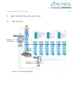
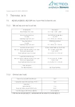
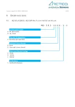
Page 44: ...Instruction manual AQ101 AQ101D AQ110P AQ01 44 48 ...

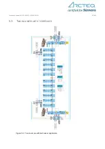
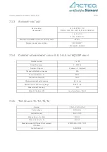
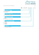
Page 45: ...Instruction manual AQ101 AQ101D AQ110P AQ01 45 48 ...

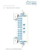
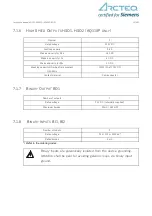
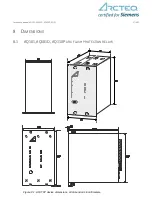
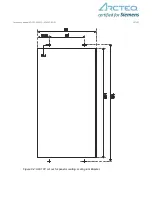
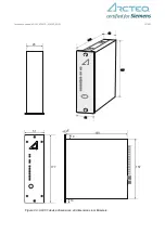
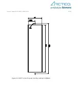
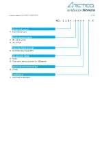
Page 46: ...Instruction manual AQ101 AQ101D AQ110P AQ01 46 48 9 2 AX001 CONNECTION FIBER ...

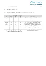
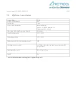
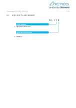
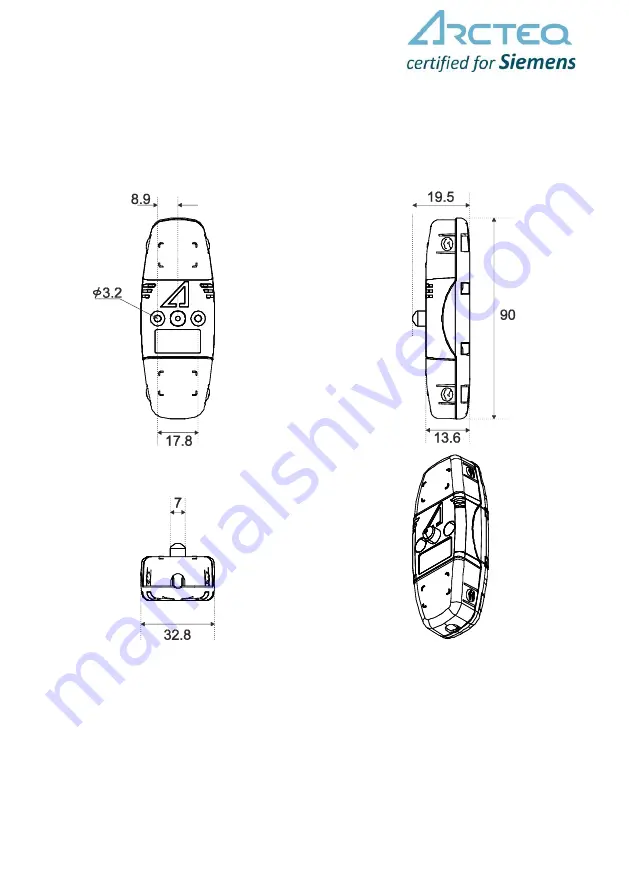
Page 47: ...Instruction manual AQ101 AQ101D AQ110P AQ01 47 48 9 3 AQ01 ARC FLASH SENSOR ...

Page 48: ...ATION Manufacturer information Arcteq Relays Ltd Finland For more information regarding SIQuench arc quenching device please contact Siemens Customer Support Center Tel 49 180 524 70 00 Fax 49 180 524 24 71 Charges depending on provider E mail support energy siemens com ...

Reviews: