7SR11 & 7SR12 Settings & Instruments Guide
©2017 Siemens Protection Devices Limited Chapter 2 Page 9 of 20
1.4 Instruments Mode
The Instrument Mode sub-menu displays key quantities and information to aid with commissioning. The following
meters are available and are navigated around by using the
▲,▼and TEST/REST buttons. The text description
shown here is the default information. Depending upon the relay model you have, you may not have all of the
meters shown.
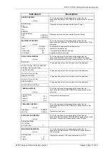
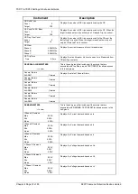
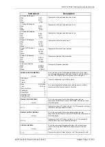
Instrument
Description
FAVOURITE METERS
→to view
This allows the user to view his previously constructed list of
‘favourite meters’ by pressing TEST/RESET
► button and the
READ DOWN button to scroll though the meters added to this sub-
group
To construct a sub-group of favourite meters, first go to the desired
meter then press ENTER this will cause a message to appear on
the LCD ‘Add To Favourites YES pressing ENTER again will add
this to the FAVOURITE METERS Sub-menu. To remove a meter
from the FAVOURITE METERS sub-menu go to that meter each in
the FAVOURITE METERS sub-menu or at its Primary location
press ENTER and the message ‘Remove From Favourites’ will
appear press ENTER again and this meter will be removed from
the FAVOURITE METERS sub-group
CURRENT METERS
→to view
This is the sub-group that includes all the meters that are
associated with Current TEST/RESET
► allows access to this
sub-group
Primary Current
Ia 0.00A
Ib 0.00A
Ic 0.00A
Displays the 3 phase currents Primary RMS values
Secondary Current
Ia 0.00A
Ib 0.00A
Ic 0.00A
Displays the 3 phase currents Secondary RMS values
Nom Current
Ia 0.00xIn ---
o
Ib 0.00xIn ---
o
Ic 0.00xIn ---
o
Displays the 3 Phase currents Nominal RMS values & phase
angles with respect to PPS voltage.
Pri Earth Current
In 0.00A
Ig 0.00A
Displays the 3 Earth currents Primary RMS values
Sec Earth Current
In 0.00A
Ig 0.00A
Displays the 3 Earth currents Secondary RMS values
Nom Earth Current
In 0.00xIn ---
o
Ig 0.00xIn ---
o
Displays the 3 Earth currents Nominal RMS values & phase angles
with respect to PPS voltage.
I Seq Components
Izps 0.00xIn --
o
Ipps 0.00xIn --
o
Inps 0.00xIn --
o
Displays the Current Sequence components Nominal RMS values
& phase angles with respect to PPS voltage.
2nd Harmonic Current
Ia 0.00xIn
Ib 0.00xIn
Ic 0.00xIn
Displays the Second Harmonic Current.
Last Trip P/F
Ia 0.00A
Ib 0.00A
Ic 0.00A
Displays the Last Trip Fault Current..
Last Trip E/F
Displays the Last Trip Fault Current..
Summary of Contents for Argus 7SR11
Page 1: ...Energy Management 7SR11 7SR12 Argus Overcurrent Relay Reyrolle Protection Devices ...
Page 2: ......
Page 4: ...7SR11 7SR12 Argus Contents 2015 Siemens Protection Devices Limited Page 2 of 2 ...
Page 170: ...7SR120 Technical Manual Chapter 4 Page 2 of 84 2017 Siemens Protection Devices Limited ...
Page 174: ...7SR120 Technical Manual Chapter 4 Page 6 of 84 2017 Siemens Protection Devices Limited ...
Page 196: ...7SR120 Technical Manual Chapter 4 Page 28 of 84 2017 Siemens Protection Devices Limited ...
Page 242: ...7SR120 Technical Manual Chapter 4 Page 74 of 84 2017 Siemens Protection Devices Limited ...
Page 244: ...7SR120 Technical Manual Chapter 4 Page 76 of 84 2017 Siemens Protection Devices Limited ...
Page 246: ...7SR120 Technical Manual Chapter 4 Page 78 of 84 2017 Siemens Protection Devices Limited ...
Page 254: ...7SR11 7SR12 Installation Guide Chapter 5 Page 2 of 32 2017 Siemens Protection Devices Limited ...
Page 358: ...7SR11 7SR12 Applications Guide Page 2 of 48 2017 Siemens Protection Devices Limited ...
Page 405: ......


