7SR11 & 7SR12 Description Of Operation
Chapter 1 Page 76 of 88 ©2017 Siemens Protection Devices Limited
5.3 CT Supervision (60CTS)
The relay has two methods of detecting a CT failure, depending on the relay model. CT Supervision is only
available in relays with four current inputs.
5.3.1
60CTS
FOR
7SR11
(60CTS-I
FOR
7SR12)
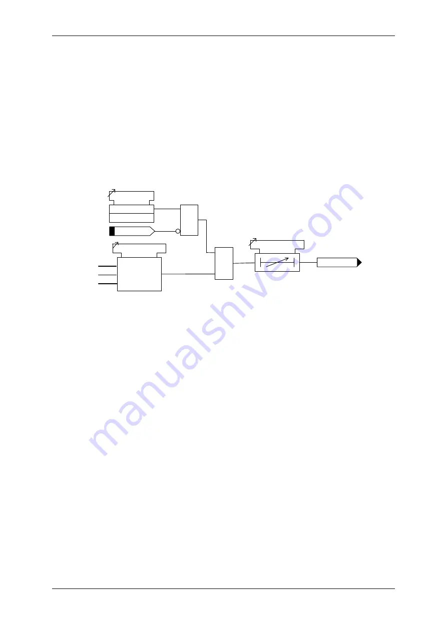
The current from each of the Phase Current Transformers is monitored. If one or two of the three input currents
falls below the CT supervision current setting
CTS I
for more than
60CTS Delay
then a CT failure output (
60CTS
Operated
) is given. If all three input currents fall below the setting, CT failure is not raised.
An output is also given to indicate the faulted phase,
60CTS-I PhA
,
60CTS-I PhB, and 60CTS-I PhC
Operation of the CT supervision elements can be inhibited from:
Inhibit 60CTS
A binary or virtual input.
60CTS Delay
IL1
IL2
IL3
60CTS I
<
Any 2 phases
but not all 3
&
Inhibit 60CTS
60CTS Element
Enabled
Disabled
&
60CTS Operated
Figure 5-3 Logic Diagram: CT Supervision Function (60CTS) – 7SR11
This function is retained in the 7SR12 as it provides phase discrimination, whereas the standard function provided
in the 7SR12 does not.
5.3.2
60CTS
FOR
7SR12
Normally the presence of negative phase sequence (NPS) current in a power system is accompanied by NPS
voltage. The presence of NPS current without NPS voltage is used to indicate a current transformer failure.
The element has a setting for NPS current level
60CTS Inps
and a setting for NPS voltage level
60CTS Vnps
If
the negative sequence current exceeds its setting while the negative sequence voltage is below its setting for
more than
60CTS Delay
then a CT failure output (
60CTS Operated
) is given.
Operation of the CT supervision elements can be inhibited from:
Inhibit 60CTS
A binary or virtual input.
Summary of Contents for Argus 7SR11
Page 1: ...Energy Management 7SR11 7SR12 Argus Overcurrent Relay Reyrolle Protection Devices ...
Page 2: ......
Page 4: ...7SR11 7SR12 Argus Contents 2015 Siemens Protection Devices Limited Page 2 of 2 ...
Page 170: ...7SR120 Technical Manual Chapter 4 Page 2 of 84 2017 Siemens Protection Devices Limited ...
Page 174: ...7SR120 Technical Manual Chapter 4 Page 6 of 84 2017 Siemens Protection Devices Limited ...
Page 196: ...7SR120 Technical Manual Chapter 4 Page 28 of 84 2017 Siemens Protection Devices Limited ...
Page 242: ...7SR120 Technical Manual Chapter 4 Page 74 of 84 2017 Siemens Protection Devices Limited ...
Page 244: ...7SR120 Technical Manual Chapter 4 Page 76 of 84 2017 Siemens Protection Devices Limited ...
Page 246: ...7SR120 Technical Manual Chapter 4 Page 78 of 84 2017 Siemens Protection Devices Limited ...
Page 254: ...7SR11 7SR12 Installation Guide Chapter 5 Page 2 of 32 2017 Siemens Protection Devices Limited ...
Page 358: ...7SR11 7SR12 Applications Guide Page 2 of 48 2017 Siemens Protection Devices Limited ...
Page 405: ......


