7SR220 Settings Guide
Unrestricted Page 12 of 107
© 2013 Siemens Protection Devices Limited
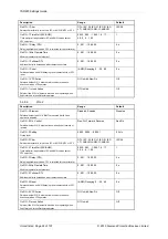
Description
Range
Default
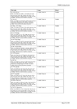
Gn Close Cct Supervision
When set to Disabled, no Close Cct Supervision elements will
be functional and all associated settings will be hidden. (The
Setting Dependencies setting being set to Disabled will make
all settings visible but will not allow them to operate).
Enabled, Disabled
Disabled
Gn Inrush Detector
When set to Disabled, no Inrush Detector elements will be
functional and all associated settings will be hidden. (The
Setting Dependencies setting being set to Disabled will make
all settings visible but will not allow them to operate).
Enabled, Disabled
Disabled
Gn Load Blinder
When set to Disabled, no Load Blinder elements will be
functional and all associated settings will be hidden. (The
Setting Dependencies setting being set to Disabled will make
all settings visible but will not allow them to operate).
Enabled, Disabled
Disabled
Gn CB Counters
When set to Disabled, no Gn CB Counter elements will be
functional and all associated settings will be hidden. (The
Setting Dependencies setting being set to Disabled will make
all settings visible but will not allow them to operate).
Enabled, Disabled
Disabled
Gn I^2t CB Wear
When set to Disabled, no Gn I^2t CB Wear elements will be
functional and all associated settings will be hidden. (The
Setting Dependencies setting being set to Disabled will make
all settings visible but will not allow them to operate).
Enabled, Disabled
Disabled
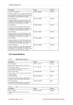
Gn Arc Flash Detector
When set to Disabled, no Arc Flash Detector elements will be
functional and all associated settings will be hidden. (The
Setting Dependencies setting being set to Disabled will make
all settings visible but will not allow them to operate).
Enabled, Disabled
Disabled
3.4. Current Prot’n
3.4.1.
Phase Overcurrent
Description
Range
Default
Gn 67 Char Angle
Maximum torque angle for phase overcurrent elements
-95, -94 ... 94, 95
45 deg
Gn 67 Minimum Voltage
Selects the directional elements minimum voltage, below
which the element will be inhibited
1, 1.5 ... 19.5, 20
1 V
Gn 67 2-out-of-3 Logic
Selects whether 2 out of 3 voting logic is enabled for phase
overcurrent elements
Enabled, Disabled
Disabled
Gn 50 Measurement
Selects whether the RMS value used by the 50 elements is
True RMS or only calculated at fundamental frequency
RMS, Fundamental
RMS
Gn 51 Measurement
Selects whether the RMS value used by the 51 elements is
True RMS or only calculated at fundamental frequency
RMS, Fundamental
RMS
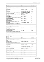
3.4.1.1.
51-1
Description
Range
Default
Gn 51-1 Element
Selects whether the 51-1 IDMTL Overcurrent element is
enabled
Disabled, Enabled
Disabled
Summary of Contents for Argus 7SR21
Page 1: ...Energy Management 7SR21 7SR22 Argus Overcurrent Relay Reyrolle Protection Devices ...
Page 2: ......
Page 4: ...Contents 7SR11 and 7SR12 Page 2 of 2 2018 Siemens Protection Devices Limited ...
Page 185: ...7SR210 Settings Guide Unrestricted 2018 Siemens Protection Devices Limited Page 61 of 61 ...
Page 277: ...7SR220 Settings Guide Unrestricted Page 72 of 107 2013 Siemens Protection Devices Limited ...
Page 382: ...7SR220 Technical Manual Chapter 4 Page 2 of 96 2017 Siemens Protection Devices Limited ...
Page 386: ...7SR220 Technical Manual Chapter 4 Page 6 of 96 2017 Siemens Protection Devices Limited ...
Page 398: ...7SR220 Technical Manual Chapter 4 Page 18 of 96 2017 Siemens Protection Devices Limited ...
Page 414: ...7SR220 Technical Manual Chapter 4 Page 34 of 96 2017 Siemens Protection Devices Limited ...
Page 466: ...7SR220 Technical Manual Chapter 4 Page 86 of 96 2017 Siemens Protection Devices Limited ...
Page 468: ...7SR220 Technical Manual Chapter 4 Page 88 of 96 2017 Siemens Protection Devices Limited ...
Page 470: ...7SR220 Technical Manual Chapter 4 Page 90 of 96 2017 Siemens Protection Devices Limited ...
Page 472: ...7SR220 Technical Manual Chapter 4 Page 92 of 96 2017 Siemens Protection Devices Limited ...
Page 643: ...Unrestricted ...


