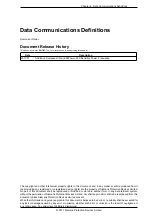
Chapter 4 - Data Communications Definitions
© 2017 Siemens Protection Devices Limited
Chapter 4 - Page 3 of 96
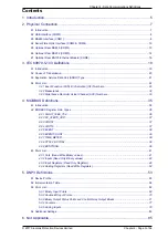
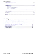
Contents
1. Introduction ............................................................................................................... 5
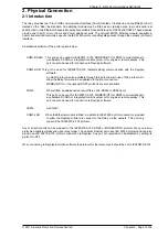
2. Physical Connection ................................................................................................. 7
2.1 Introduction ......................................................................................................................................... 7
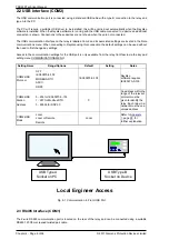
2.2 USB Interface (COM2) ........................................................................................................................ 8
2.3 RS485 Interface (COM1) .................................................................................................................... 8
2.4 Serial Fibre Optic Interface (COM3 & COM4) .................................................................................... 10
2.5 Optional Rear RS485 (COM3) .......................................................................................................... 13
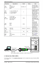
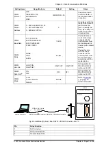
2.6 Optional Rear RS232 (COM3) .......................................................................................................... 14
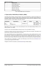
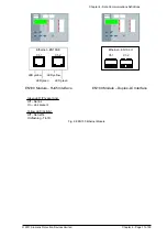
2.7 Optional Rear EN100 Ethernet Module (COM3) ................................................................................ 16
3. IEC 60870-5-103 Definitions .................................................................................. 19
3.1 Introduction ....................................................................................................................................... 19
3.2 Cause of Transmission ..................................................................................................................... 20
3.3 Application Service Data Unit (ASDU) Type ...................................................................................... 21
3.4 Point List .......................................................................................................................................... 22
3.4.1 Event Function (FUN) & Information (INF) Numbers............................................................. 22
3.4.2 Measurands ........................................................................................................................ 32
3.4.3 Disturbance Recorder Actual Channel (ACC) Numbers ........................................................ 33
4. MODBUS Definitions .............................................................................................. 35
4.1 Introduction ....................................................................................................................................... 35
4.2 MODBUS Register Data Types ......................................................................................................... 36
4.2.1 FLOAT_IEEE_754 ............................................................................................................... 36
4.2.2 FP_32BITS_3DP ................................................................................................................. 37
4.2.3 UINT32 ............................................................................................................................... 37
4.2.4 UINT16 ............................................................................................................................... 37
4.2.5 EVENT ................................................................................................................................ 38
4.2.6 EVENTCOUNT .................................................................................................................... 39
4.2.7 TIME_METER ..................................................................................................................... 39
4.2.8 STR32 & STR64 ................................................................................................................. 39
4.2.9 BITSTRING ......................................................................................................................... 39
4.3 Point List .......................................................................................................................................... 41
4.3.1 Coils (Read Write Binary values) ......................................................................................... 41
4.3.2 Inputs (Read Only Binary values) ........................................................................................ 42
4.3.3 Input Registers (Read Only Registers) ................................................................................. 49
4.3.4 Holding Registers (Read Write Registers) ............................................................................ 52
5. DNP3 Definitions .................................................................................................... 53
5.1 Device Profile ................................................................................................................................... 53
5.2 Implementation Table ........................................................................................................................ 56
5.3 Point List .......................................................................................................................................... 62
5.3.1 Binary Input Points .............................................................................................................. 62
5.3.2 Double Bit Input Points ........................................................................................................ 70
5.3.3 Binary Output Status Points and Control Relay Output Blocks .............................................. 71
5.3.4 Counters ............................................................................................................................. 77
5.3.5 Analog Inputs ...................................................................................................................... 79
5.4 Additional Settings ............................................................................................................................ 83
6. Not Applicable ........................................................................................................ 85
Summary of Contents for Argus 7SR21
Page 1: ...Energy Management 7SR21 7SR22 Argus Overcurrent Relay Reyrolle Protection Devices ...
Page 2: ......
Page 4: ...Contents 7SR11 and 7SR12 Page 2 of 2 2018 Siemens Protection Devices Limited ...
Page 185: ...7SR210 Settings Guide Unrestricted 2018 Siemens Protection Devices Limited Page 61 of 61 ...
Page 277: ...7SR220 Settings Guide Unrestricted Page 72 of 107 2013 Siemens Protection Devices Limited ...
Page 382: ...7SR220 Technical Manual Chapter 4 Page 2 of 96 2017 Siemens Protection Devices Limited ...
Page 386: ...7SR220 Technical Manual Chapter 4 Page 6 of 96 2017 Siemens Protection Devices Limited ...
Page 398: ...7SR220 Technical Manual Chapter 4 Page 18 of 96 2017 Siemens Protection Devices Limited ...
Page 414: ...7SR220 Technical Manual Chapter 4 Page 34 of 96 2017 Siemens Protection Devices Limited ...
Page 466: ...7SR220 Technical Manual Chapter 4 Page 86 of 96 2017 Siemens Protection Devices Limited ...
Page 468: ...7SR220 Technical Manual Chapter 4 Page 88 of 96 2017 Siemens Protection Devices Limited ...
Page 470: ...7SR220 Technical Manual Chapter 4 Page 90 of 96 2017 Siemens Protection Devices Limited ...
Page 472: ...7SR220 Technical Manual Chapter 4 Page 92 of 96 2017 Siemens Protection Devices Limited ...
Page 643: ...Unrestricted ...

