7SR220 Technical Manual
Chapter 4 - Page 62 of 96
© 2017 Siemens Protection Devices Limited
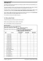
5.3 Point List
The tables below identify all the default data points provided by the implementation of the Triangle MicroWorks, Inc.
DNP 3.0 Slave Source Code Library.
This protocol can be set to use any or all of the relays hardware interfaces (USB, Fibre Optic, RS232 and RS485)
where fitted. The relay can communicate simultaneously on all ports regardless of protocol used.
The Station Address of the port being used must be set to a suitable address within the range 0 - 65534 to enable
communication. This can be set by the
Communications Menu : COM
n-xxxxx
Station Address
setting.
Communication via DNP3 over Ethernet requires external devices. Please refer to the documents
TCPIP Catalogue
Sheet
and
TCPIP Interface Technical Guidance Notes
for more information.
The information shown below is the default configuration.
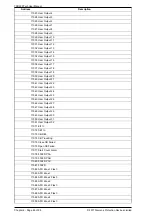
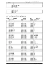
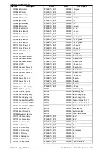
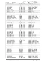
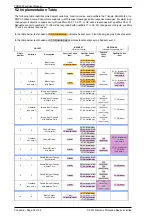
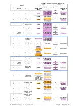
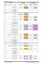
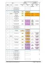
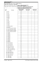
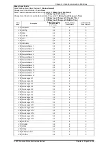
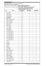
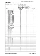
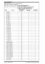
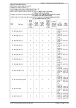
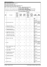
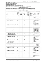
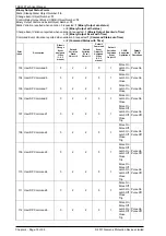
5.3.1 Binary Input Points
The default binary input event buffer size is set to allow 100 events.
Binary inputs are by default returned in a class zero interrogation.
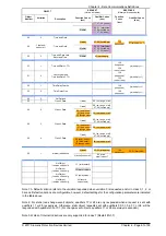
Note, not all points listed here apply to all builds of devices.
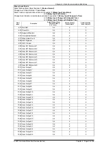
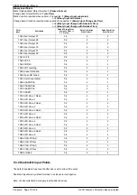
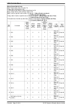
Binary Input Points
Static (Steady-State) Object Number:
1 (Packed Format)
Change Event Object Number:
1 (w/o Time)
Static Variation reported when variation 0 requested:
1 (Binary Input w/o status)
or
2 (Binary Input with status)
Change Event Variation reported when variation 0 requested:
1 (Binary Input Change w/o Time)
or
2 (Binary Input Change with Absolute Time)
or
3 (Binary Input Change with Relative Time)
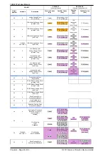
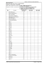
Point
Index
Description
Default Change Event
Assigned Class (1,
2, 3 or none)
Default Variation
Static Object 1
Default Variation
Event Object 2
1 Binary Input 1
0,2
2
2
2 Binary Input 2
0,2
2
2
3 Binary Input 3
0,2
2
2
4 Binary Input 4
0,2
2
2
5 Binary Input 5
0,2
2
2
6 Binary Input 6
0,2
2
2
7 Binary Input 7
0,2
2
2
8 Binary Input 8
0,2
2
2
9 Binary Input 9
0,2
2
2
10 Binary Input 10
0,2
2
2
11 Binary Input 11
0,2
2
2
12 Binary Input 12
0,2
2
2
13 Binary Input 13
0,2
2
2
35 Remote Mode
0,2
2
2
36 Out Of Service Mode
0,2
2
2
37 Local Mode
0,2
2
2
38 Local & Remote
0,2
2
2
40 General Trip
0,2
2
2
41 Trip Circuit Fail
0,2
2
2
42 Start/Pick-up L1
0,2
2
2
43 Start/Pick-up L2
0,2
2
2
Summary of Contents for Argus 7SR21
Page 1: ...Energy Management 7SR21 7SR22 Argus Overcurrent Relay Reyrolle Protection Devices ...
Page 2: ......
Page 4: ...Contents 7SR11 and 7SR12 Page 2 of 2 2018 Siemens Protection Devices Limited ...
Page 185: ...7SR210 Settings Guide Unrestricted 2018 Siemens Protection Devices Limited Page 61 of 61 ...
Page 277: ...7SR220 Settings Guide Unrestricted Page 72 of 107 2013 Siemens Protection Devices Limited ...
Page 382: ...7SR220 Technical Manual Chapter 4 Page 2 of 96 2017 Siemens Protection Devices Limited ...
Page 386: ...7SR220 Technical Manual Chapter 4 Page 6 of 96 2017 Siemens Protection Devices Limited ...
Page 398: ...7SR220 Technical Manual Chapter 4 Page 18 of 96 2017 Siemens Protection Devices Limited ...
Page 414: ...7SR220 Technical Manual Chapter 4 Page 34 of 96 2017 Siemens Protection Devices Limited ...
Page 466: ...7SR220 Technical Manual Chapter 4 Page 86 of 96 2017 Siemens Protection Devices Limited ...
Page 468: ...7SR220 Technical Manual Chapter 4 Page 88 of 96 2017 Siemens Protection Devices Limited ...
Page 470: ...7SR220 Technical Manual Chapter 4 Page 90 of 96 2017 Siemens Protection Devices Limited ...
Page 472: ...7SR220 Technical Manual Chapter 4 Page 92 of 96 2017 Siemens Protection Devices Limited ...
Page 643: ...Unrestricted ...

