7SR210 & 7SR220 Commissioning & Maintenance Guide
© 2013 Siemens Protection Devices Limited
Page 71 of 82
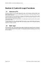
3.4
Broken Conductor. (46BC)
7SR22
46
BC
46
NPS
(x2)
37
(x2)
49
50
BF
V
L1
(V
A
)
V
L2
(V
B
)
V
L3
(V
C
)
V
4
(V
X
)
I
L1
(I
A
)
81
HBL
2
37
(x2)
49
50
BF
I
L2
(I
B
)
81
HBL
2
37
(x2)
49
50
BF
I
L3
(I
C
)
81
HBL
2
60
CTS
I
4
(I
G
)
I
5
(I
SEF
)
74
TCS
NOTE: The use of some
functions are mutually exclusive
67/
50
(x4)
67/
51
(x4)
67/
50N
(x4)
67/
50
(x4)
67/
50
(x4)
67/
51
(x4)
67/
51
(x4)
67/
51N
(x4)
67/
50G
(x4)
67/
51G
(x4)
67/
50S
(x4)
67/
51S
(x4)
64
H
27
59
27
59
(x4)
27
59
(x4)
27
59
(x4)
47
(x2)
81
(x6)
79
Optional
59N
(x2)
81
HBL
2N
60
VTS
51V
51V
51V
37G
(x2)
37S
(x2)
51c
60
CTS-
I
60
CTS-
I
60
CTS-
I
37
50
BF
37
50
BF
25
50
AFD
50
AFD
50
AFD
51c
51c
51c
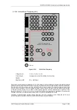
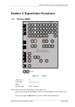
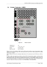
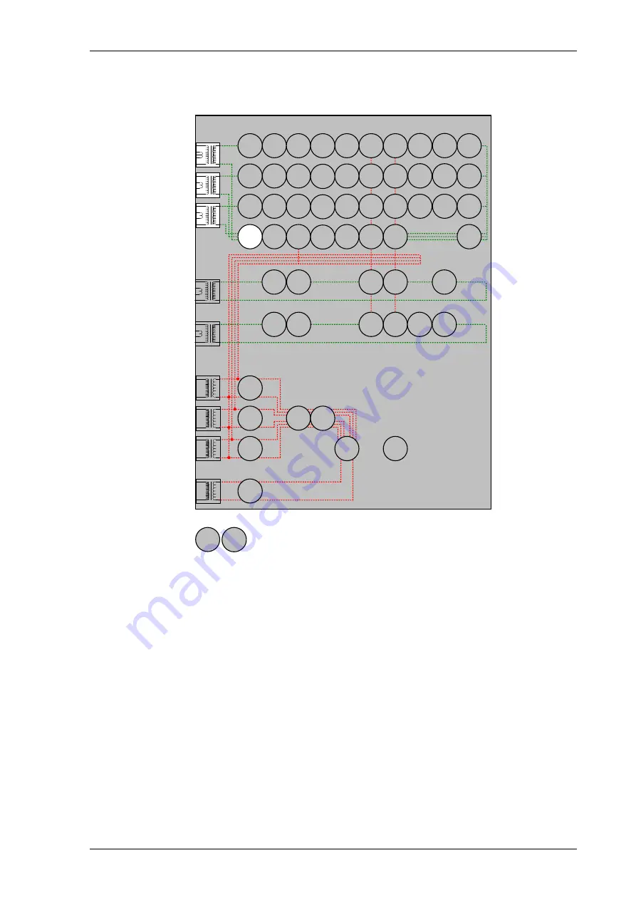
Figure 3.4-1
Broken Conductor
Voltage Inputs:
n/a
Current Inputs:
I
L1
(I
A
), I
L2
(I
B
), I
L3
(I
C
),
Disable:
51N, 46IT, 46DT
Map Pickup LED:.
46BC - Self Reset
Broken Conductor uses the ratio of NPS current to PPS current to detect an open circuit conductor. These
quantities can be produced directly from many advanced test sets but with limited equipment the following
approach can be applied.
Apply 3P balanced current with normal phase rotation direction. This current will consist of PPS alone, no NPS or
ZPS.
Increase 1 phase current magnitude in isolation to produce NPS. The single phase unbalance current will contain
equal quantities of ZPS, NPS and PPS. The NPS component will be 1/3 of the unbalance current and the total
PPS component will be value of the original balanced 3P current plus 1/3 of the additional unbalance current. i.e.
as the single phase unbalance current increases, the ratio of NPS to PPS will also increase. The levels of each
sequence component current can be monitored in the
Current Meters
in
Instruments Mode
.
Summary of Contents for Argus 7SR21
Page 1: ...Energy Management 7SR21 7SR22 Argus Overcurrent Relay Reyrolle Protection Devices ...
Page 2: ......
Page 4: ...Contents 7SR11 and 7SR12 Page 2 of 2 2018 Siemens Protection Devices Limited ...
Page 185: ...7SR210 Settings Guide Unrestricted 2018 Siemens Protection Devices Limited Page 61 of 61 ...
Page 277: ...7SR220 Settings Guide Unrestricted Page 72 of 107 2013 Siemens Protection Devices Limited ...
Page 382: ...7SR220 Technical Manual Chapter 4 Page 2 of 96 2017 Siemens Protection Devices Limited ...
Page 386: ...7SR220 Technical Manual Chapter 4 Page 6 of 96 2017 Siemens Protection Devices Limited ...
Page 398: ...7SR220 Technical Manual Chapter 4 Page 18 of 96 2017 Siemens Protection Devices Limited ...
Page 414: ...7SR220 Technical Manual Chapter 4 Page 34 of 96 2017 Siemens Protection Devices Limited ...
Page 466: ...7SR220 Technical Manual Chapter 4 Page 86 of 96 2017 Siemens Protection Devices Limited ...
Page 468: ...7SR220 Technical Manual Chapter 4 Page 88 of 96 2017 Siemens Protection Devices Limited ...
Page 470: ...7SR220 Technical Manual Chapter 4 Page 90 of 96 2017 Siemens Protection Devices Limited ...
Page 472: ...7SR220 Technical Manual Chapter 4 Page 92 of 96 2017 Siemens Protection Devices Limited ...
Page 643: ...Unrestricted ...

