7SR210 & 7SR220 Applications Guide
Page 32 of 48
©2018 Siemens Protection Devices Limited
Section 4: Control Functions
4.1 Auto-reclose Applications
Automatic circuit reclosing is extensively applied to overhead line circuits where a high percentage of faults that
occur are of a transient nature. By automatically reclosing the circuit-breaker the function attempts to minimise the
loss of supply to the customer and reduce the need for manual intervention.
The function supports up to 4 ARC sequences. That is, 4 x Trip / Recloses followed by a Trip & Lockout. A lockout
condition prevents any further attempts, automatic or manual, to close the circuit-breaker. The number of
sequences selected depends upon the type of faults expected. If there are a sufficient percentage of semi-
permanent faults which could be burnt away, e.g. fallen branches, a multi shot scheme would be appropriate.
Alternatively, if there is a high likelihood of permanent faults, a single shot scheme would minimise the chances of
causing damage by reclosing onto a fault. In general, 80% of faults will be cleared by a single Trip and Reclose
sequence. A further 10% will be cleared by a second Trip and Reclose. Different sequences can be selected for
different fault types (Phase/Earth/Sensitive Earth faults).
The Deadtime is the interval between the trip and the CB close pulse being issued. This is to allow for the line to
go ‘dead’ after the fault is cleared. The delay chosen is a compromise between the need to return the line to
service as soon as possible and prevented unnecessary trips through re-closing too soon. The Reclaim Time is
the delay following a re-closure before the line can be considered back in service. This should be set long enough
to allow for protection operation for the same fault, but not so long that two separate faults could occur in the
same Autoreclose (ARC) sequence and cause unnecessary lockouts.
Since large fault currents could potentially damage the system during a prolonged ARC sequence, there are also
settings to identify which protection elements are High-sets and these can cause an early termination of the
sequence.
Where a relay is to operate as part of an ARC scheme involving a number of other relays, the feature attempts to
clear any faults quickly without regard to normal fault current grading. It does this by setting each Trip element to
be either Delayed or Instantaneous. Instantaneous Trips are set to operate at just above maximum load current
with small delays while Delayed Trips are set to suit actual fault levels and with delays suitable for current
grading.
A typical sequence would be 2 Instantaneous Trips followed by a Delayed Trip & Lockout: -
•
When any fault occurs, the relay will trip instantaneously and then reclose.
•
If this does not clear the fault, the relay will do the same again.
•
If this still does not clear the fault, the fault is presumed to be permanent and the next Trip will be
Delayed and so suitable for grading with the rest of the network. Thus allowing downstream
protection time to operate.
•
This Trip will Lockout the ARC sequence and prevent further recloses.
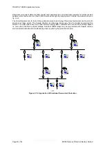
It is important that all the relays in an ARC scheme shadow this process – advancing through their own ARC
sequences when a fault is detected by an element pickup even though they are not actually causing a trip or
reclose. This is termed Sequence Co-ordination and prevents an excessive number of recloses as each
successive relay attempts to clear the fault in isolation. For this reason each relay in an ARC scheme must be set
with identical Instantaneous and Delayed sequence of trips.
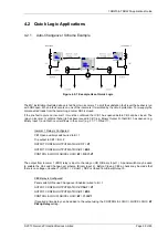
Figure 4.1-1 Sequence Co-ordination
Summary of Contents for Argus 7SR21
Page 1: ...Energy Management 7SR21 7SR22 Argus Overcurrent Relay Reyrolle Protection Devices ...
Page 2: ......
Page 4: ...Contents 7SR11 and 7SR12 Page 2 of 2 2018 Siemens Protection Devices Limited ...
Page 185: ...7SR210 Settings Guide Unrestricted 2018 Siemens Protection Devices Limited Page 61 of 61 ...
Page 277: ...7SR220 Settings Guide Unrestricted Page 72 of 107 2013 Siemens Protection Devices Limited ...
Page 382: ...7SR220 Technical Manual Chapter 4 Page 2 of 96 2017 Siemens Protection Devices Limited ...
Page 386: ...7SR220 Technical Manual Chapter 4 Page 6 of 96 2017 Siemens Protection Devices Limited ...
Page 398: ...7SR220 Technical Manual Chapter 4 Page 18 of 96 2017 Siemens Protection Devices Limited ...
Page 414: ...7SR220 Technical Manual Chapter 4 Page 34 of 96 2017 Siemens Protection Devices Limited ...
Page 466: ...7SR220 Technical Manual Chapter 4 Page 86 of 96 2017 Siemens Protection Devices Limited ...
Page 468: ...7SR220 Technical Manual Chapter 4 Page 88 of 96 2017 Siemens Protection Devices Limited ...
Page 470: ...7SR220 Technical Manual Chapter 4 Page 90 of 96 2017 Siemens Protection Devices Limited ...
Page 472: ...7SR220 Technical Manual Chapter 4 Page 92 of 96 2017 Siemens Protection Devices Limited ...
Page 643: ...Unrestricted ...

