7SR210 & 7SR220 Description of Operation
Unrestricted ©2018 Siemens Protection Devices Limited
Page 71 of 94
Phase Difference
&
Phase Decreasing
?
SLIP
Line U/ V
Block
Bus U/ V
BLock
V Block
D
&
COZ Slip Frequency Setting
Block
Block
Block
&
CB Close Time
F
Angle
Slip Within Range ?
COZ
Close
&
(> Split Slip & < COZ slip)
Split Slip Setting
Live Line
Live Bus
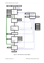
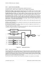
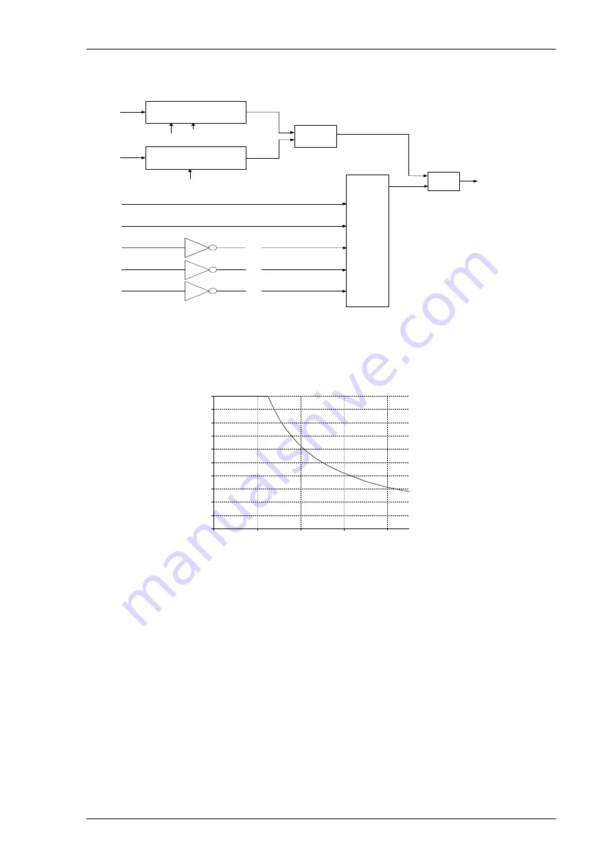
Figure 4.9.8-1
Close On Zero Function
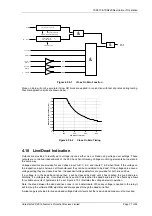
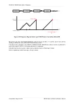
Close on Zero will not be accurate if slow CB times are applied in conjunction with fast slip rates during testing.
Practical application limits are shown below: -
0
0.2
0.4
0.6
0.8
1
1.2
1.4
1.6
1.8
2
0
200
400
600
800
CB Close Time (ms)
Ma
xi
mu
m
S
lip
Fre
qu
enc
y (Hz
)
Figure 4.9.8-2
Close On Zero Timing
4.10 Live/Dead Indication
Outputs are provided to identify each voltage input as either Live or Dead using voltage user settings. These
outputs are controlled independently of the 25 Check Synchronising Voltage monitoring elements but operate in
the same way.
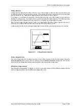
Voltage detectors are provided for each phase input A, B, C & X and inputs Y & Z when fitted. If the voltage on
the respective input is below a set threshold level they can be considered to be ‘dead’. If the voltages are above a
voltage setting they are classed as ‘live’. Independent voltage detectors are provided for both line and bus.
If a voltage is in the dead band range then it will be classed as dead until it has reached the live band area.
Similarly, if a voltage is live, it continues to be live until it has reached the dead band area. This effectively allows
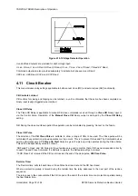
for variable amounts of hysteresis to be set. Figure 4.10-1 illustrates the voltage detector operation.
Note: the area between the dead and live zones is not indeterminate. When any voltage is applied to the relay it
will ramp up the software RMS algorithm and always pass through the dead zone first.
A wide range is provided for live and dead voltage detector levels but the live and dead zones must not overlap.
Summary of Contents for Argus 7SR21
Page 1: ...Energy Management 7SR21 7SR22 Argus Overcurrent Relay Reyrolle Protection Devices ...
Page 2: ......
Page 4: ...Contents 7SR11 and 7SR12 Page 2 of 2 2018 Siemens Protection Devices Limited ...
Page 185: ...7SR210 Settings Guide Unrestricted 2018 Siemens Protection Devices Limited Page 61 of 61 ...
Page 277: ...7SR220 Settings Guide Unrestricted Page 72 of 107 2013 Siemens Protection Devices Limited ...
Page 382: ...7SR220 Technical Manual Chapter 4 Page 2 of 96 2017 Siemens Protection Devices Limited ...
Page 386: ...7SR220 Technical Manual Chapter 4 Page 6 of 96 2017 Siemens Protection Devices Limited ...
Page 398: ...7SR220 Technical Manual Chapter 4 Page 18 of 96 2017 Siemens Protection Devices Limited ...
Page 414: ...7SR220 Technical Manual Chapter 4 Page 34 of 96 2017 Siemens Protection Devices Limited ...
Page 466: ...7SR220 Technical Manual Chapter 4 Page 86 of 96 2017 Siemens Protection Devices Limited ...
Page 468: ...7SR220 Technical Manual Chapter 4 Page 88 of 96 2017 Siemens Protection Devices Limited ...
Page 470: ...7SR220 Technical Manual Chapter 4 Page 90 of 96 2017 Siemens Protection Devices Limited ...
Page 472: ...7SR220 Technical Manual Chapter 4 Page 92 of 96 2017 Siemens Protection Devices Limited ...
Page 643: ...Unrestricted ...

