7SR210 & 7SR220 Description of Operation
Unrestricted ©2018 Siemens Protection Devices Limited
Page 21 of 94
2.6
Current Inputs
Four current inputs are provided in the 7SR21 relay and five inputs are provided in the 7SR22 relay. Current
inputs are located on the Analogue Input module. Terminals are available for both 1 A and 5 A inputs. Current is
sampled at 1600 Hz for both 50 Hz and 60 Hz system frequencies. Protection and monitoring functions of the
relay use either the Fundamental Frequency RMS or the True RMS value of current appropriate to the individual
function. The waveform recorder samples and displays current input waveforms at 1600 Hz.
NB: The Relay has a flat frequency response measuring harmonic currents up to and including the 50th Harmonic
but does not measure the content at the aliasing frequencies i.e. 800 Hz (16th harmonic) + 1600 Hz (32nd
harmonic) + 2400 Hz (48th harmonic).
2.7
Voltage Inputs
Four voltage inputs are provided in the 7SR22 relay. Voltage inputs are located on the Analogue Input module.
Voltage is sampled at 1600 Hz for both 50 Hz and 60 Hz system frequencies. Protection and monitoring functions
of the relay use fundamental frequency voltage measurement. The waveform recorder samples and displays
voltage input waveforms at 1600 Hz.
2.8
Binary Inputs
The binary inputs are operated from a suitably rated dc supply.
Relays are fitted with 3, 9, 13, 19, 33 or 39 binary inputs (BI). The user can assign any binary input to any of the
available functions (INPUT CONFIG > INPUT MATRIX).
The Power Supply module includes the relay basic I/O. The module includes 3 x BI and 6 x BO.
Non-directional (7SR21) relays have an additional 6 x BI on the analogue module.
Additional I/O modules may be fitted, these provide 10 x BI.
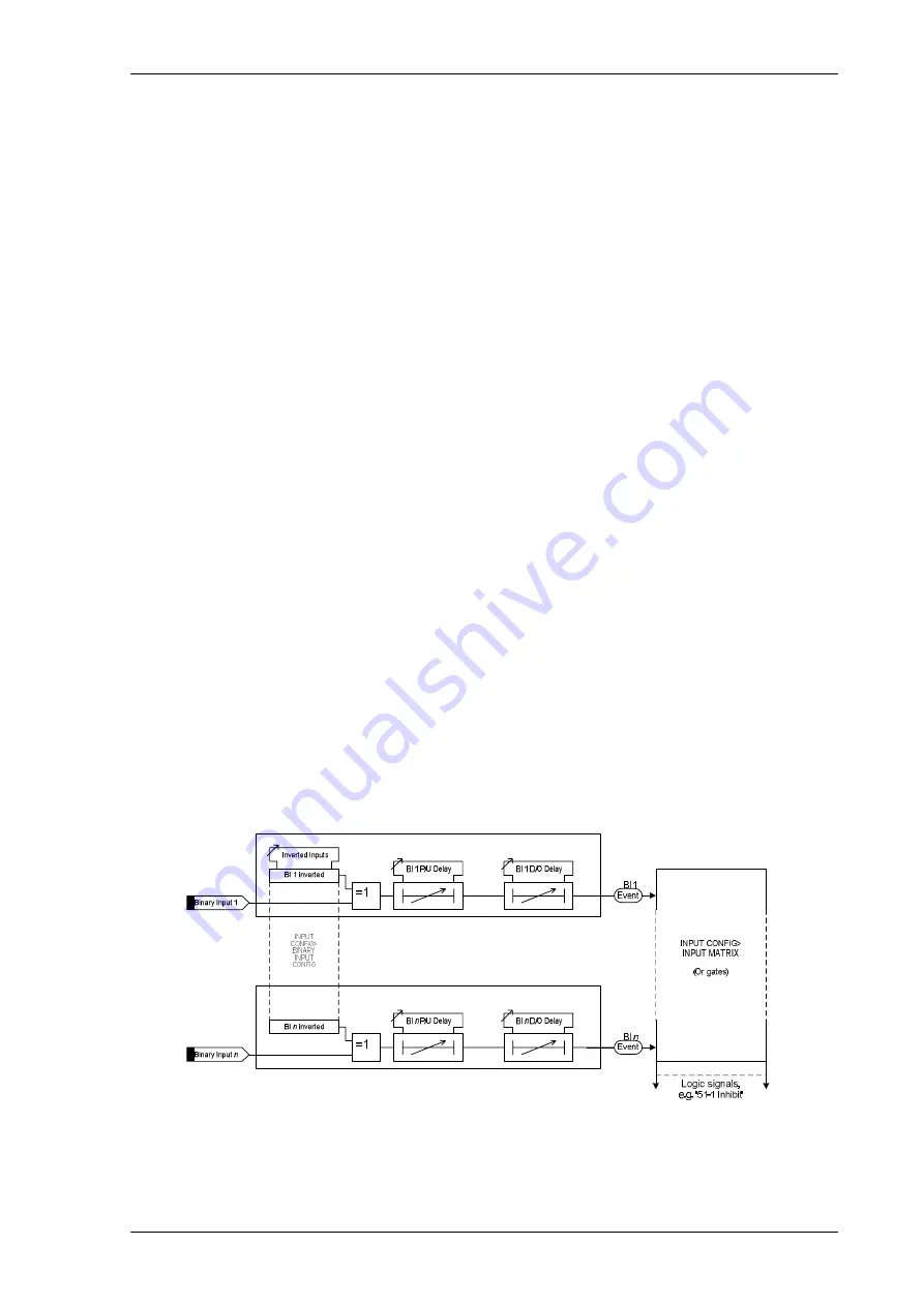
Pick-up (PU) and drop-off (DO) time delays are associated with each binary input. Where no pick-up time delay
has been applied the input may pick up due to induced ac voltage on the wiring connections (e.g. cross site
wiring). The default pick-up time of 20 ms provides ac immunity. Each input can be programmed independently.
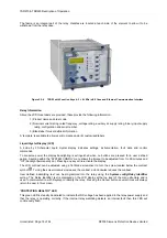
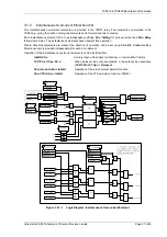
Each input may be logically inverted to facilitate integration of the relay within the user scheme. When inverted the
relay indicates that the BI is energised when no d.c. is applied. Inversion occurs before the PU & DO time delay,
see fig. 2.8-1.
Each input may be mapped to any front Fascia indication LED and/or to any Binary output contact and can also
be used with the internal user programmable logic. This allows the relay to provide panel indications and alarms.
The binary inputs are sampled every 5 ms.
Figure 2.8-1 Binary Input Logic
Summary of Contents for Argus 7SR21
Page 1: ...Energy Management 7SR21 7SR22 Argus Overcurrent Relay Reyrolle Protection Devices ...
Page 2: ......
Page 4: ...Contents 7SR11 and 7SR12 Page 2 of 2 2018 Siemens Protection Devices Limited ...
Page 185: ...7SR210 Settings Guide Unrestricted 2018 Siemens Protection Devices Limited Page 61 of 61 ...
Page 277: ...7SR220 Settings Guide Unrestricted Page 72 of 107 2013 Siemens Protection Devices Limited ...
Page 382: ...7SR220 Technical Manual Chapter 4 Page 2 of 96 2017 Siemens Protection Devices Limited ...
Page 386: ...7SR220 Technical Manual Chapter 4 Page 6 of 96 2017 Siemens Protection Devices Limited ...
Page 398: ...7SR220 Technical Manual Chapter 4 Page 18 of 96 2017 Siemens Protection Devices Limited ...
Page 414: ...7SR220 Technical Manual Chapter 4 Page 34 of 96 2017 Siemens Protection Devices Limited ...
Page 466: ...7SR220 Technical Manual Chapter 4 Page 86 of 96 2017 Siemens Protection Devices Limited ...
Page 468: ...7SR220 Technical Manual Chapter 4 Page 88 of 96 2017 Siemens Protection Devices Limited ...
Page 470: ...7SR220 Technical Manual Chapter 4 Page 90 of 96 2017 Siemens Protection Devices Limited ...
Page 472: ...7SR220 Technical Manual Chapter 4 Page 92 of 96 2017 Siemens Protection Devices Limited ...
Page 643: ...Unrestricted ...

