7SR210 & 7SR220 Description of Operation
Unrestricted Page 70 of 94
©2018 Siemens Protection Devices Limited
4.9.7
System Synchronising Mode
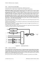
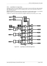
For the relay to issue a System Sync Close the following conditions have to be met: -
Both the Bus and Line voltages must be considered Live by the Voltage Monitoring elements.
25 System Sync Angle
– the phase difference between the line and bus voltages has to be less than the phase
angle setting value
and the phase angle has to be decreasing
before the element will issue a valid close signal.
25 System Sync Slip
, [if Enabled] – the frequency difference between line and bus has to be less than the slip
frequency setting value. Slip frequency must be above the
25 Split Slip
setting to avoid reversion to Check
Synchronising conditions. The settings for
25 System Sync Slip
and
25 Split Slip
must differ by at least 20 mHz.
25 System Sync Timer
, [if Enabled] – the phase angle and voltage blocking features have to be within their
parameters for the length of the slip timer setting. If either the phase angle or the voltage elements fall outside of
their limits the slip timer is reset. If they subsequently come back in then the slip timer has to time out before an
output is given. (This ensures that a close output will not be given if there is a transient disturbance on the
system due to e.g. some remote switching operations).
25 Line Undervolts, [if Enabled] – the line voltage has to be above the line under-voltage setting value and also
above 5V for an output to be given.
25 Bus Undervolts, [if Enabled] – the bus voltage has to be above the line under-voltage setting value and also
above 5V for an output to be given.
25 Volt Differential, [if Enabled] – the difference between the line and bus voltages has to be less than the V
detector setting value for an output to be given.
The System Synchronising operation of the relay will only be started after a System Split is detected as described
in section 4.9.6 during an autoreclose or manual close sequence.
Phase Within Range ?
AND
Phase Decreasing ?
SLIP
Line U/V
Block
Bus U/V
BLock
V Block
D
Phase Angle Setting
&
Slip Frequency Setting
Block
Block
Block
&
Slip Timer
Setting
Slip Timer
F
Angle
Slip Within Range ?
SystemSync
Close
Live Line
Live Bus
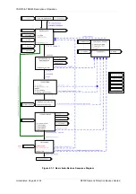
Figure 4.9.7-1
System Sync Function
4.9.8
Close on Zero Mode
If the
25 DAR Split Mode
or
25 MC Split Mode
is set
to COZ
the relay will apply a Close-On-Zero to the respective
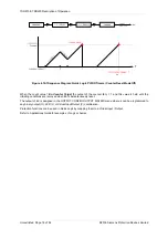
closing operation if the synchronising mode changes to System Split. The measured slip frequency and the
measured phase difference are used to provide a Close Pulse which will close the CB when the phase difference
is reducing and timed with the setting
25 CB Close Time
such that the instant of closure is when the phase
difference is zero. The slip frequency must be less than the
25 COZ Slip Freq
but greater than the
25 Split Slip
setting to avoid reversion to Check Synchronising conditions.
Since this feature is part of the System Synchronising function,
25 System Sync
must also be set to
Enabled
.
Summary of Contents for Argus 7SR21
Page 1: ...Energy Management 7SR21 7SR22 Argus Overcurrent Relay Reyrolle Protection Devices ...
Page 2: ......
Page 4: ...Contents 7SR11 and 7SR12 Page 2 of 2 2018 Siemens Protection Devices Limited ...
Page 185: ...7SR210 Settings Guide Unrestricted 2018 Siemens Protection Devices Limited Page 61 of 61 ...
Page 277: ...7SR220 Settings Guide Unrestricted Page 72 of 107 2013 Siemens Protection Devices Limited ...
Page 382: ...7SR220 Technical Manual Chapter 4 Page 2 of 96 2017 Siemens Protection Devices Limited ...
Page 386: ...7SR220 Technical Manual Chapter 4 Page 6 of 96 2017 Siemens Protection Devices Limited ...
Page 398: ...7SR220 Technical Manual Chapter 4 Page 18 of 96 2017 Siemens Protection Devices Limited ...
Page 414: ...7SR220 Technical Manual Chapter 4 Page 34 of 96 2017 Siemens Protection Devices Limited ...
Page 466: ...7SR220 Technical Manual Chapter 4 Page 86 of 96 2017 Siemens Protection Devices Limited ...
Page 468: ...7SR220 Technical Manual Chapter 4 Page 88 of 96 2017 Siemens Protection Devices Limited ...
Page 470: ...7SR220 Technical Manual Chapter 4 Page 90 of 96 2017 Siemens Protection Devices Limited ...
Page 472: ...7SR220 Technical Manual Chapter 4 Page 92 of 96 2017 Siemens Protection Devices Limited ...
Page 643: ...Unrestricted ...

