2
INSTALLATION
Remove all system power before installation, first battery and then AC.
(To power up, connect the AC first and then the battery.)
1. Remove the card from its protective bag. Do
not touch the gold edge of the board.
2. Refer to the CSG-M configuration printout for
the address of the module.
3. Set the card address on switch S1 using
dipswitches SW1 - SW4.
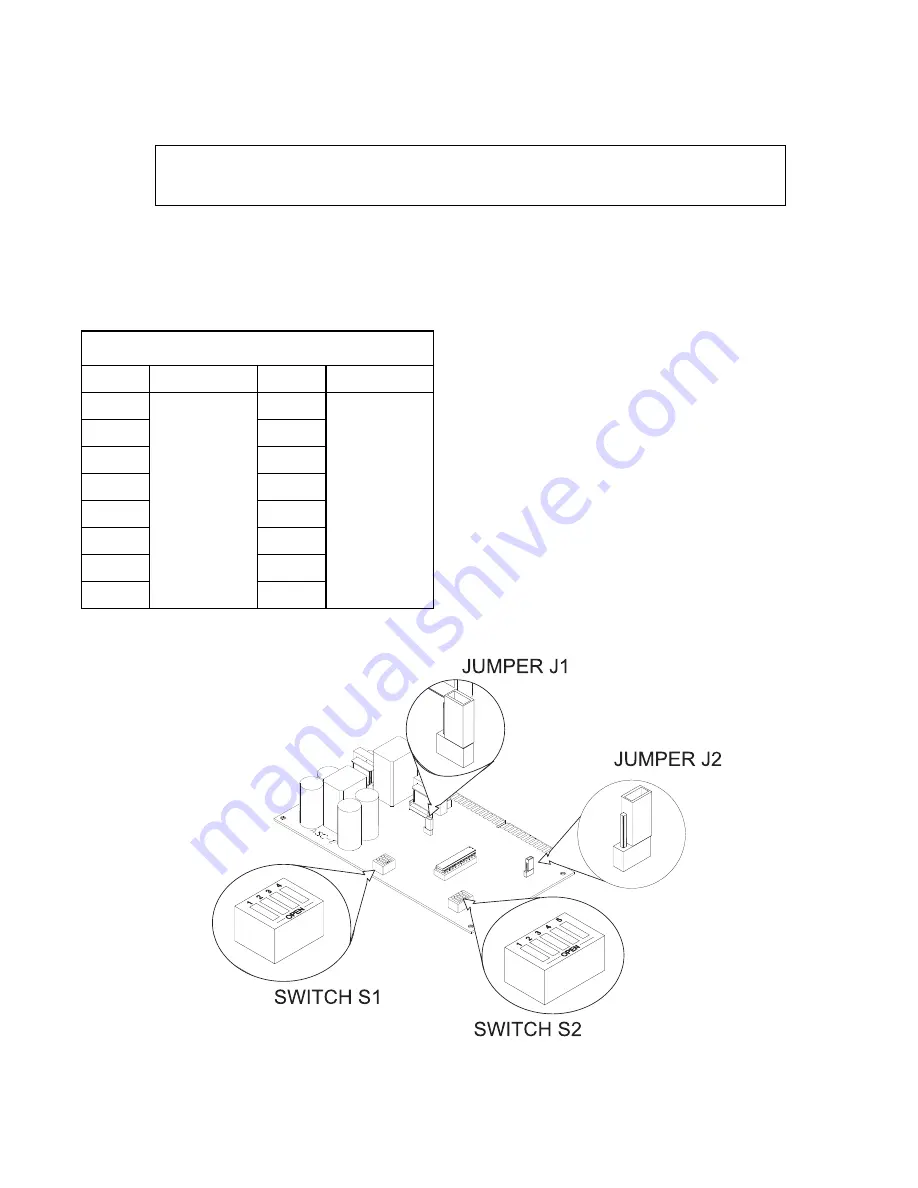
a. Refer to Figure 2 for the location of S1.
b. Refer to Table 1 for switch settings.
c. Set the card address (See NOTE below).
NOTE: To open a dipswitch,
press down on
the side of the dipswitch marked OPEN.
To close a dipswitch, press down on the
side of the dipswitch opposite the side
marked OPEN.
To open a slide switch,
push the slide
to the side opposite the side marked
ON. To close a slide switch, push the
slide to the side marked ON.
X
= SWITCH CLOSED OR
ON, O
= SWITCH OPEN OR
OFF
TABLE 1
ADDR
4
3
2
1 ADDR
4
3
2
1
ILLEGAL O O O O 8
X O O O
1
O O O X 9
X O O X
2
O O X O 10
X O X O
3
O O X
X 11
X O X
X
4
O X O O ILLEGAL X
X O O
5
O X O X ILLEGAL X
X O X
6
O X
X O ILLEGAL X
X
X O
7
O X
X
X ILLEGAL X
X
X
X
Figure 2
Locating Switches S1 and S2 and Jumpers J1 and J2 on the ASC-2


