background image

Document No. 129-420 
Installation Instructions  
December 13, 2004 

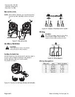
Manual Override 

NOTE: 

When EAS is installed, you can still access the 
manual override capability as shown in Figure 
11. 

0

0

GEB

GBB/GIB

GCA

GMA

EA1

185R1


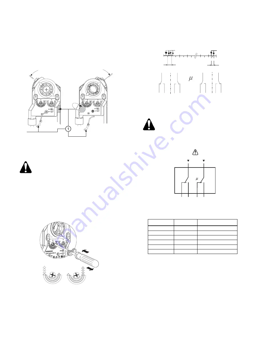
Figure 11.  Manual Override. 

Auxiliary Switches 

CAUTION: 


There should be no load on the actuator 
when setting the auxiliary switches.  


Setting the Switches 

With the actuator in the full-closed (0°) position, press in 
and turn with a Phillips screwdriver to the desired 
setting. Release pressure to set the switch. 
The switch is now set. 
 

~3.5


mm


max.


10N

EA1

186R1

5

25

45 55

65

75

85

35

15

85

75

65

55 45 35

25

15

5

5

25

45 55

65

75

85

35

15

85

75

65

55 45 35

25

15

5


Figure 12.  Press In, Turn to Adjust, Release to Set Switch. 


A

B

S1

S1

S4

S4

S2 S3

S2 S3

S5 S6

S5 S6

(Q12)

(Q14)

(Q14)

(Q12)

(Q22)

(Q24)

(Q22)

(Q24)

(Q1

1)

(Q1

1)

(Q21)

(Q21)

A

B

5

5

85

2

20

30

70

90

0

10

EA1

187R1


Figure 13.  Example of Switches Set to 5° and 85°. 

Wiring 

WARNING: 

Do not mix operations. Apply only line voltage 
or only Class 2 voltages to the switching 
outputs of both auxiliary switches A and B.  


A

24


Vac...250


V/6(2)


A

(Q12)

(Q14)

(Q24)

(Q22)

S2 S3

S5 S6

S1

S4

(Q1

1)

(Q21)

B


EA1

189R1


Figure 14.  Wiring Diagram. 

Wiring Designation 

Wire Code 

Color 

Switch - Function 

S1 Gray/red  A 

Input 

S2 

Gray/blue 

A – NC 

S3 

Gray/pink 

A – NO 

S4 Black/red  B 

Input 

S5 

Black/blue 

B – NC 

S6 

Black/pink 

B – NO 


Page 4 of 5 

Siemens Building Technologies, Inc.


Summary of Contents for ASC77.2U

Page 1: ...e 0 to 45 Switch B 0 to 90 with 5 intervals Recommended usage 45 to 90 Switching hysteresis 2 UL listed to UL 873 cUL certified to Canadian Standard C22 2 No 24 93 Electromagnetic compatibility 89 336 EEC Agency certification Low voltage directive 73 23 EEC Conduit Connection Threaded 1 2 inch NSPT flex only Shipping Weight 1 1 lb 0 48 kg Warning Caution Notations WARNING Personal injury loss of l...

Page 2: ...0 EA1190R1 PUSH Figure 4 Insert Shaft Adapter at Position A New Spring Return Actuators 1 Without the shaft adapter installed using the hex wrench wind the manual override one full revolution and release the wrench See Figure 5 The actuator will return to the 0 position and the preload is now removed EA1192R1 1 Turn Manu al Override Figure 5 2 Manually install the shaft adapter against the externa...

Page 3: ...e Figure 8 step 2 and Figure 9 step 2 EA1182R1 b f Figure 8 For GMA GEB Actuators Use Top Screw Holes f EA1181R1 b 2 1 Figure 9 For GCA GBB GIB Actuators Use the Bottom Screw Holes Mounting External Auxiliary Switch to Actuator 1 Nest the alignment peg of the EAS position adapter ring into the notch See Figure 10 The EAS lies flush against the face of the actuator EA1183R1 9 5 1 5 lb in 1 1 Nm 0 2...

Page 4: ... 75 85 35 15 85 75 65 55 45 35 25 15 5 5 25 45 55 65 75 85 35 15 85 75 65 55 45 35 25 15 5 Figure 12 Press In Turn to Adjust Release to Set Switch A B S1 S1 S4 S4 S2 S3 S2 S3 S5 S6 S5 S6 Q12 Q14 Q14 Q12 Q22 Q24 Q22 Q24 Q11 Q11 Q21 Q21 A B 5 5 85 2 20 30 70 90 0 10 EA1187R1 Figure 13 Example of Switches Set to 5 and 85 Wiring WARNING Do not mix operations Apply only line voltage or only Class 2 vol...

Page 5: ... in specifications and models as design improvements are introduced OpenAir is a trademark of Siemens Building Technologies Inc Other product or company names mentioned herein may be the trademarks of their respective owners 2004 Siemens Building Technologies Inc Siemens Building Technologies Inc 1000 Deerfield Parkway Buffalo Grove IL 60089 4513 Your feedback is important to us If you have commen...

Reviews: