background image

Data Library

2.5  Setup Parameters

ATC5300
Modbus Communication Protocol, Edition 03/2011, A5E02469001-02

23

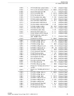
3109h

1

P2.10 Switch close pulse duration

1

600

Unsigned integer

310Ah

1

P2.11 Load not powered timeout

0

3600 

À

Unsigned integer

310Bh

1

P2.12 Inhibit auto retransfer

0

¿

Unsigned integer

310Ch

1

P2.13 Pre-transfer time

0

300 

À

Unsigned integer

310Dh

1

P2.14 Post-transfer time

0

300 

À

Unsigned integer

310Eh

1

P2.15 Generator start delay

0

900

Unsigned integer

310Fh

1

P2.16 Generator cooling time

1

3600

Unsigned integer

3110h

1

P2.17 Generator rotation time

0

14 

¿

Unsigned integer

3111h

1

P2.18 Generator rotation hour

0

23

Unsigned integer

3112h

1

P2.19 Generator rotation minutes

0

59

Unsigned integer

3113h

1

P2.20 Min battery voltage

69

100 

À

Unsigned integer

3114h

1

P2.21 Max battery voltage

100

141 

Á

Unsigned integer

3115h

1

P2.22 Battery alarm delay

0

60

Unsigned integer

3116h

1

P2.23 Set clock at power-on

0

Â

Unsigned integer

3117h

P2.24 Voltage control in manual

0

¿

Unsigned integer

3118h

P2.25 Continuous command in 
OFF / RESET mode

0

Â

Unsigned integer

3119h

P2.26 EJP start delay

0

3600 

À

Unsigned integer

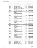
3200h

1

P3.01 Min voltage drop out

70

98

Unsigned integer

3201h

1

P3.02 Min voltage pick up

75

100

Unsigned integer

3202h

1

P3.03 Min voltage delay

1

9000

Unsigned integer

3203h

1

P3.04 Max voltage drop out

102

…1

21 

Á

Unsigned integer

3204h

1

P3.05 Max voltage pick up

100

115

Unsigned integer

3205h

1

P3.06 Max voltage delay

1

9000

Unsigned integer

3206h

1

P3.07 Phase loss threshold

59

85 

À

Unsigned integer

3207h

1

P3.08 Phase loss delay

1

300

Unsigned integer

3208h

1

P3.09 Asymmetry threshold

2

21 

Á

Unsigned integer

3209h

1

P3.10 Asymmetry delay

1

9000

Unsigned integer

320Ah

1

P3.11 Min frequency

79

100 

À

Unsigned integer

320Bh

1

P3.12 Min frequency delay

1

9000

Unsigned integer

320Ch

1

P3.13 Max frequency

100

121 

Á

Unsigned integer

320Dh

1

P3.14 Max frequency delay

1

9000

Unsigned integer

320Eh

1

P3.15 Line 1 ok delay (when line 2 
not OK)

1

3600

Unsigned integer

320Fh

1

P3.16 Line 1 ok delay (when line 2 
OK)

1

3600

Unsigned integer

3300h

1

P4.01 Min voltage drop out

0

3600 

À

Unsigned integer

3301h

1

P4.02 Min voltage pick up

0

¿

Unsigned integer

3302h

1

P4.03 Min voltage delay

0

300 

À

Unsigned integer

3303h

1

P4.04 Max voltage drop out

0

300 

À

Unsigned integer

3304h

1

P4.05 Max voltage pick up

0

900

Unsigned integer

3305h

1

P4.06 Max voltage delay

1

3600

Unsigned integer

3306h

1

P4.07 Phase loss threshold

0

14 

¿

Unsigned integer

3307h

1

P4.08 Phase loss delay

0

23

Unsigned integer

3308h

1

P4.09 Asymmetry threshold

0

59

Unsigned integer

Summary of Contents for ATC5300

Page 1: ...ATC5300 Automatic Transfer Controller Modbus Communication Protocol Edition 03 2011 A5E02469001 02 General Information 1 Data Library 2 s ...

Page 2: ... Disclaimer of Liability We have reviewed the contents of this publication to ensure consistency with the hardware and software described Since variance cannot be precluded entirely we cannot guarantee full consistency However the information in this publication is reviewed regularly and any necessary corrections are included in subsequent editions DANGER indicates that death or severe personal in...

Page 3: ... 07 Read Exception Status 10 1 9 Function 17 Report Slave ID 11 1 10 Errors 11 1 11 Function 16 Preset Multiple Register 12 1 12 Modbus ASCII Protocol 12 1 13 CRC Calculation CHECKSUM for RTU 14 1 14 Technical Support 16 2 Data Library 17 2 1 Data Provided 17 2 2 Status Bits 18 2 3 Commands 21 2 4 Parameter Setting 22 2 5 Setup Parameters 22 2 6 Real Time Clock 25 2 7 Event Log Reading 25 2 8 Even...

Page 4: ...ATC5300 4 Modbus Communication Protocol Edition 03 2011 A5E02469001 02 ...

Page 5: ... controllers support the communication protocols Modbus RTU and Modbus ASCII on the RS 232 and RS 485 serial ports Using this function it is possible to read the device status and to control the units through the dedicated remote control software SENTRON SOFTWARE ATC third party supervision software SCADA or through other intelligent devices supporting Modbus like PLCs ...

Page 6: ...with a P while the two following digits indicate the number of the parameter within the menu The first parameter is P1 01 i e menu P1 parameter 01 Press keys A or C to scroll the parameters of the same menu Press keys E or F to browse the different menus The digit identifying the parameter is shown on LINE 1 display while the current setting is shown on LINE 2 display Press keys B or D to change t...

Page 7: ...e Default P7 01 RS 232 Address 1 245 1 P7 02 RS 232 Baud Rate 2400 4800 9600 19200 38400 9600 baud P7 03 RS 232 Protocol Rtu ASC ASCII Mod ASCII modem rtu P7 04 RS 232 Parity Non None Odd EvE Even non P7 05 RS 485 Baud Rate 1 245 1 P7 06 RS 485 Baud Rate 2400 4800 9600 19200 38400 9600 baud P7 07 RS 485 Protocol Rtu ASC ASCII Mod ASCII modem rtu P7 08 RS 485 Parity Non None Odd EvE Even non ...

Page 8: ...f one message and the beginning of another This time must be at least 3 5 times the time required to send one character The ATC measures the time that elapse from the reception of one character and the following If this time exceeds the time necessary to send 3 5 characters at the selected baudrate then the next character will be considered as the first of a new message 1 5 Modbus Functions The av...

Page 9: ...in the table If the measure address is not included in the table or the number of requested registers exceeds 60 the ATC will return an error code see error table Master query In the above example slave 08 is requested for 8 consecutive registers beginning with address 10h Thus registers from 10h to 17h will be returned As usual the message ends with the CRC checksum Slave response The response is...

Page 10: ...rom MAN to AUT and vice versa can be possibly executed sending the addresses and the values reported in Table 4 Master message Slave response The slave response is an echo to the query that is the slave sends back to the master the address and the new value of the variable 1 8 Function 07 Read Exception Status This function allows to read the status of the automatic transfer switch Master query Th...

Page 11: ...he queried function ORed with 80 Hex followed by an error code byte The following table shows the error codes sent by the slave to the master Table 1 Error Codes Slave address 08h Function 11h MSB CRC C6h LSB CRC 7Ch Slave address 08h Function 11h Byte count 04h Data 01 Device type 61h Data 02 SW revision 04h Data 03 Hardware revision 00h Data 04 Parameter revision 01h MSB CRC h LSB CRC h CODE ERR...

Page 12: ...ication port has the following structure The Address field holds the serial address of the slave destination device The Function field holds the code of the function that must be executed by the slave The Data field contains data sent to the slave or data received from the slave in response to a query The maximum allowable length is of 60 consecutive registers The LRC field allows the master and s...

Page 13: ...tion Read input register 00 03 Address of the required register L2 voltage of line 1 decreased by one 00 02 Number of registers to be read beginning from address 04 EF LRC Checksum CRLF ASCII 0Dh 0Ah Message end delimiter The ATC answer is the following Whereas ASCII 3Ah message start delimiter 08 Multimeter address Slave 08 04 Function requested by the master 04 Number of bytes sent by the multim...

Page 14: ...RC Calculation Workflow XOR exclusive or n number of information bits POLY calculation polynomial of the CRC 16 1010 0000 0000 0001 Generating polynomial 1 x 2 x 15 x 16 In the CRC 16 the 1st byte transmitted is the least significant one CRC xor BYTE CRC n 0 CRC right s hift carry over CRC x or POLY CRC n n 1 nex t BYTE end mes sage End n 7 Hex FFFF CRC n o no ye s yes ...

Page 15: ...1 Carry 1 load polynominal 1010 0000 0000 0001 Execute xor with the polynominal 1000 0100 1111 1110 Execute 7th right shift 0100 0010 0111 1111 0 Execute 8th right shift 0010 0001 0011 1111 1 Carry 1 load polynominal 1010 0000 0000 0001 Load the second byte of the frame 0000 0111 Execute xor with the polynominal 1000 0001 0011 1001 Second byte of the frame Execute 1st right shift 0100 0000 1001 11...

Page 16: ...tion 03 2011 A5E02469001 02 1 14 Technical Support For further assistance refer to Technical Support on the Internet Internet address of Technical Support http www siemens com lowvoltage technical support Execute 8th right shift 0001 0010 0100 0001 0 CRC Result 0001 0010 0100 0001 12h 41h ...

Page 17: ...V Unsigned long 16h 2 Voltage of line 2 L2 L3 V Unsigned long 18h 2 Voltage of line 2 L3 L1 V Unsigned long 1Ah 2 Frequency of line 1 Hz 10 Unsigned long 1Ch 2 Frequency of line 2 Hz 10 Unsigned long 1Eh 2 Battery voltage DC power supply VDC 10 Unsigned long 20h 2 Total operation time s Unsigned long 22h 2 Line 1 ok total time s Unsigned long 24h 2 Line 2 ok total time s Unsigned long 26h 2 Line 1...

Page 18: ...it breaker timeout 3 A04 Line 2 circuit breaker timeout 4 A05 Line 1 wrong phase sequence 5 A06 Line 2 wrong phase sequence 6 A07 Load not powered timeout 7 A08 Generator not available 8 A09 Emergency 9 not used 10 Breaker 1 Trip 11 Breaker 1 Withdrawn 12 Breaker 2 Trip 13 Breaker 2 Withdrawn 14 31 not used ADDRESS WORDS FUNCTION FORMAT 2070h 1 Front panel keyboard status Unsigned integer 2071h 1 ...

Page 19: ...EST mode 5 ON OFF Line 1 6 Line 2 measure selection 7 Line 1 measure selection 8 15 Not used Bit Input 0 Input terminal 4 1 status 1 Input terminal 4 2 status 2 Input terminal 4 3 status 3 Input terminal 4 4 status 4 Input terminal 4 5 status 5 Input terminal 4 6 status 6 Input terminal 4 7 status 7 Input terminal 4 8 status 8 15 Not used Bit Output 0 Output terminal 1 1 status 1 Output terminal 1...

Page 20: ...below min 7 Voltage above max 8 Voltage asymmetry 9 Voltage phase loss 10 Frequency below min 11 Frequency above max 12 Wrong phase sequence 13 All line parameters ok 14 15 Not used Bit Breaker Status 0 Breaker closed 1 Trip alarm 2 Withdrawn alarm 3 Command status 1 close 4 Close command output 5 Open command output 6 15 Not used Bit Input Functions Status 0 Line 1 breaker closed feedback 1 Line ...

Page 21: ...t Output Functions Status 0 Line 1 breaker open 1 Line 1 breaker close 2 Line 2 breaker open 3 Line 2 breaker close 4 Global alarm 5 Generator 1 start 6 Generator 2 start 7 ATS ready 8 Load shed 9 Pre transfer 10 Post transfer 11 15 Not used ADDRESS WORDS FUNCTION FORMAT 2F00h 1 Operative mode change Unsigned integer 2F01h 1 Device reset warm boot À Unsigned integer 2F02h 1 Setup parameters back t...

Page 22: ...2 manual switching 1 OFF mode 2 MAN mode 3 AUT mode 4 TEST mode 5 Line 1 manual switching 6 Line 2 measure selection 7 Line 1 measure selection 8 15 Not used ADDRESS WORDS PARAMETER RANGE FORMAT 3000h 1 P1 01 Nominal voltage 100 690 Unsigned integer 3001h 1 P1 02 VT ratio 100 999 Unsigned integer 3002h 1 P1 03 Wiring configuration 0 3 Unsigned integer 3003h 1 P1 04 Voltage control mode 0 2 Unsigne...

Page 23: ...201h 1 P3 02 Min voltage pick up 75 100 Unsigned integer 3202h 1 P3 03 Min voltage delay 1 9000 Unsigned integer 3203h 1 P3 04 Max voltage drop out 102 121 Á Unsigned integer 3204h 1 P3 05 Max voltage pick up 100 115 Unsigned integer 3205h 1 P3 06 Max voltage delay 1 9000 Unsigned integer 3206h 1 P3 07 Phase loss threshold 59 85 À Unsigned integer 3207h 1 P3 08 Phase loss delay 1 300 Unsigned inte...

Page 24: ...Unsigned integer 3406h 1 P5 07 Programmable Input 1 function 0 19 Unsigned integer 3407h 1 P5 08 Programmable Input 1 function 0 19 Unsigned integer 3500h 1 P6 01 Programmable output 1 function 0 14 Unsigned integer 3501h 1 P6 02 Programmable output 1 function 0 14 Unsigned integer 3502h 1 P6 03 Programmable output 1 function 0 14 Unsigned integer 3503h 1 P6 04 Programmable output 1 function 0 14 ...

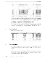
Page 25: ...icated by the event counter If the head of the circular buffer is reached pos 1 then it is necessary to move to the last position pos 100 tail and then go back until the most recent event is reached again Time stamp values are returned in compacted format in three registers containing each a couple of data For instance register 2100h holds in the MSB the hours and in LSB minutes The same criteria ...

Page 26: ...02h 1 Event pos 1 Month Year 0 12 0 99 Unsigned integer 2103h 1 Event pos 1 Event code 1 225 Unsigned integer 2104h 1 Event pos 2 Hours Minutes 0 23 0 59 Unsigned integer 2105h 1 Event pos 2 Seconds Day 0 59 0 31 Unsigned integer 2106h 1 Event pos 2 Month Year 0 12 0 99 Unsigned integer 2107h 1 Event pos 2 Event code 1 225 Unsigned integer 228Ch 1 Event pos 100 Hours Minutes 0 23 0 59 Unsigned int...

Page 27: ... voltage into limits 45 Line 1 voltage out of limits 46 Line 1 frequency into limits 47 Line 1 frequency out of limits 48 Line 1 phase sequence ok 49 Line 1 phase sequence wrong 50 Line 1 asymmetry into limits 51 Line 1 asymmetry out of limits 52 Line 1 switch closed 53 Line 1 switch opened 54 Line 1 voltage below minimum 55 Line 1 voltage above minimum 56 Line 1 phase failure 57 Line 1 frequency ...

Page 28: ... alarm A10 91 Begin of alarm Line 1 breaker Trip 92 Begin of alarm Line 2 breaker Trip 93 Begin of alarm Line 1 breaker Withdrawn 94 Begin of alarm Line 2 breaker Withdrawn 95 Begin of alarm A15 96 Begin of alarm A16 97 Begin of alarm A17 98 Begin of alarm A18 99 Begin of alarm A19 100 Begin of alarm A20 101 End of alarm A01 Low battery voltage 102 End of alarm A02 High battery voltage 103 End of ...

Page 29: ...fied 140 Real time clock modified 141 Setup parameters reset to default 142 Keyboard unlocked 143 Keyboard locked 150 Event log cleared 151 Hour meters cleared 152 Operation counters cleared 210 Begin of remote control 211 End of remote control 212 Incoming call from modem 213 Modem line closed 214 Modem call to PC 215 Connection to PC ok 216 Connection to PC failed 217 SMS sent to user 1 218 SMS ...

Page 30: ...2 2 2 3 B300 AC1 B300 B300 AC1 1 3 1 2 1 1 4 1 9 1 RS485 TR 6 4 A 6 3 B 6 2 SG 6 1 RS232 9 3 9 4 N L3 9 2 L2 L1 220 240V 0V DC SUPPLY 5 3 5 2 5 1 8 4 N L3 8 3 8 2 L2 L1 8 1 7 3 7 2 7 1 3 2 3 7 250V 5A AC1 3 8 B300 3 6 3 5 B300 AC1 250V 5A 3 3 3 4 2 3 250V 5A B300 AC1 250V 5A AC1 3 1 B300 B300 AC1 250V 12A 2 2 2 1 1 1 250V 12A B300 250V 5A AC1 AC1 1 3 1 2 B300 N 8 4 4 8 TR 6 4 4 6 4 7 4 5 4 4 4 2 4...

Reviews: