background image

Chapter 2 – Applications 


Application 6700 Slave Mode 


13 

Siemens Industry, Inc. 

Owner's Manual 

125-5093 

Building Technologies 


2015-10-14 

Application 6700 Slave Mode 

Application 6700 is the slave mode application for the BACnet Fume Hood Controller 

(see 

Ordering Notes

 for product numbers). Slave mode is the default application that 

comes up when power is first applied to the controller. Slave mode provides no control. 

Its purpose is to allow the operator to perform equipment checkout before a control 

application is put into effect and to set some basic controller parameters (CTLR 

ADDRESS, APPLICATION, and so on).  
 

Summary of Contents for BACnet

Page 1: ...125 5093 Building Technologies 2015 10 14 BACnet Fume Hood Controller Vertical Sash with Damper or Venturi Air Valve and 2 Position Constant Volume with Damper Owner s Manual ...

Page 2: ......

Page 3: ...Equipment 9 Chapter 2 Applications 10 Basic Operation 10 Application 6740 Fume Hood Controller 2 Position Constant Volume 10 Application 6741 Fume Hood Controller Vertical Sash Configuration with Damper 11 Application 6742 Fume Hood Controller Vertical Sash Configuration with Venturi Air Valve 12 Application 6700 Slave Mode 13 Chapter 3 Point Database 14 Chapter 4 Basic Service and Maintenance 21 ...

Page 4: ...The Glossary describes the terms and acronyms used in this manual The Index helps you locate information presented in this manual Manual Conventions The following table lists conventions to help you use this manual in a quick and efficient manner Convention Examples Numbered Lists 1 2 3 indicate a procedure with sequential steps 1 Turn OFF power to the field panel 2 Turn ON power to the field pane...

Page 5: ...able lists the safety symbols used in this manual to draw attention to important information Symbol Meaning Description NOTICE CAUTION Equipment damage may occur if a procedure or instruction is not followed as specified For online documentation the NOTICE displays in white with a blue background CAUTION Minor or moderate injury may occur if a procedure or instruction is not followed as specified ...

Page 6: ...of the controller with cover and mounting bracket see Figure BACnet Fume Hood Controller The controller board is the central computing controlling component of the system The following applications are covered Vertical Sash Vertical Sash with Damper Application 6741 Vertical Sash with Venturi Application 6742 2 Position CV with Damper 2 Position with a Constant Volume Application 6740 Slave Mode A...

Page 7: ...Analog AO 3 Analog Actuation Application 6742 Operator Display Panel ODP Application 6740 Application 6741 Application 6742 AO 2 flow signal 1 to 10 Vdc Application 6740 Application 6741 Application 6742 Digital Autozero Solenoid in Offboard Air Module DO 8 Application 6740 Application 6741 Application 6742 Optional Alarm DO 7 Application 6740 Application 6741 Application 6742 Optional OFF Mode DO...

Page 8: ... Generic Controller I O Layout See Wiring Diagram for application specific details Power Wiring Communication Wiring The controller connects to the field panel by means of a Floor Level Network FLN trunk Communication wiring connects to the three screw terminals on the controller labeled positive negative and reference ...

Page 9: ...ve RX 9 Indicates when flashing that the controller is receiving information from the field panel Transmit TX 10 Indicates when flashing that the controller is transmitting information to the field panel BST Basic Sanity Test BST 11 Indicates when flashing ON and OFF once per second that the controller is functioning properly Actuators Actuators used with the BACnet Fume Hood Controller include el...

Page 10: ...ications Application 6740 Fume Hood Controller 2 Position Constant Volume This application is designed for use with a constant volume or two position fume hood in a manifold fume hood exhaust system Two position fume hoods have an individual exhaust damper connected to a central fan The application modulates the exhaust flow control device to maintain a high or low flow setpoint based on inputs fr...

Page 11: ...f fume hood sash configurations connected to a manifold fume hood exhaust system The sash configurations include Bench style fume hoods single vertical sash Dual Bench style fume hoods side by side single vertical sash Floor Mounted style fume hoods two vertical sashes one on top of the other WARNING The application cannot detect a broken wire to the analog input for the second sash An external sa...

Page 12: ...ide range of fume hood sash configurations connected to a manifold fume hood exhaust system The sash configurations include Bench style fume hoods single vertical sash Dual Bench style fume hoods side by side single vertical sash Floor Mounted style fume hoods two vertical sashes one on top of the other WARNING The application cannot detect a broken wire to the analog input for the second sash An ...

Page 13: ...ation for the BACnet Fume Hood Controller see Ordering Notes for product numbers Slave mode is the default application that comes up when power is first applied to the controller Slave mode provides no control Its purpose is to allow the operator to perform equipment checkout before a control application is put into effect and to set some basic controller parameters CTLR ADDRESS APPLICATION and so...

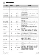
Page 14: ...een pressed When the operator presses the EMERGENCY PURGE button the point is ON the red LED is illuminated the alarm sounds and EEE and EMERGENCY MODE display at the ODP If pressed again then the point is OFF This point can be commanded by a field panel GEN FAILURE 08 6740 6741 6742 Indicates a hardware failure for example the sash sensor with an ON or OFF status The red LED is illuminated the al...

Page 15: ...en the alarm condition clears or another alarm is initiated OCC UNOCC 20 6741 6742 OCC or UNOCC point controls which face velocity setpoint to use OCC FV SET or UNOCC FV SET STARTUP MODE 21 6740 6741 6742 Toggles the ODP from normal operation to OFF mode In OFF mode the alarms do not sound the ODP displays OFF and the RED LED is on LEFT SWITCH 22 6741 6742 6700 Indicates if the left auxiliary butt...

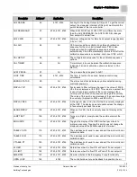
Page 16: ...ates that the contact is closed OFF indicates that the contact is open Actual status of a contact connected to the controller ON indicates that the contact is closed OFF indicates that the contact is open AO 1 39 All Spare analog output is a 0 to 10 Vdc output AO 3 40 6740 6741 6700 Spare analog output is a 0 to 10 Vdc output EXH AO3 40 6742 Control signal for Venturi General Exhaust Valve 0 10V E...

Page 17: ...6742 The open area in square feet SQM of the fume hood face which includes the fixed area and accounts for the bypass area CAL SASH POS 55 6741 6742 User defined value used during calibration of the sash sensor to describe the current position of the sash in inches cm CAL SASH LOC 56 6741 6742 User defined value MIN or MAX used during the calibration sequence to indicate if the minimum or maximum ...

Page 18: ...o the associated flow rate STARTUP DI4 78 6740 Determines if DI4 is used to change the STARTUP MODE EXH VLV STAT 79 6742 PASS or FAIL point used to indicate if the last calibration attempt passed EXH MAX 80 6741 6742 6700 Maximum flow setpoint allowed EXH MAX will override the FVEL STPT if the calculated FLOW STPT is greater than EXH MAX EXH HI STPT 80 6740 The high flow setpoint used in EXH STPT ...

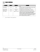
Page 19: ...2 Factor used to filter out large changes in the value of FACE VEL that is displayed at the ODP This value is a percent that is used to average a portion of the current average face velocity with a portion of the previous average face velocity The value of this point is a percentage of the current average face velocity Application 6740 uses EXH VOL DISPLAY RES 107 6740 6741 6742 A change of value ...

Page 20: ...n the ODP AVE EXH VOL 126 6740 The filtered exhaust volume that displays on the ODP PPCL STATE 127 6740 6741 6742 Indicates that customized programming has been added in addition to the normal control strategy of the application being used This point is read as LOADED or EMPTY A status of LOADED indicates that there is PPCL programming in the controller and it is providing unique control to meet a...

Page 21: ...emoving power to a locally powered controller is to turn OFF the power to the 24 Vac transformer The recommended method of removing power to a controller on a power cable even to service a single controller is to turn OFF the power at the transformer NOTE When removing power to a controller to perform maintenance or service make sure that the person in charge of the facility is aware of this and t...

Page 22: ...event of a power failure or a reset these values are retrieved from the controller s permanent memory and are used by the controller unless overridden by a field panel If one of the following conditions occurs the controller will activate safety features present in its fail safe mode Sensor failure Loss of power Upon controller power loss communication with the controller is also lost The controll...

Page 23: ...by means of Field Level Network FLN cfm Cubic Feet per Minute Chilled Beam A cooling device that provides a cooling system by taking care of both the sensible and latent heat gains of a room in a single package by a series of chilled water coils mounted near or in the ceiling Coupled with a CV or VAV terminal ventilation system a chilled beam induces air movement over the coil in the way that it d...

Page 24: ...containing a microprocessor for centralized control and monitoring of system components and equipment controllers Floating Control The combination of a modulating controlled device with the use of a pair of two position outputs The control signal will either activate one or the other outputs to drive the controlled device towards its open or closed position When both outputs are off the controlled...

Page 25: ...independent Variable Air Volume VAV room temperature control system in which the temperature drives an airflow setpoint such that the air volume delivered to the space is independent of variations in the duct static pressure PID Proportional Integral Derivative RTS Room Temperature Sensor setpoint Data point that stores a value such as a temperature setting In contrast points that monitor inputs s...

Page 26: ...at has more than two states A DI input is a physical input point that receives a two state signal unbundle Term used to describe the entering of a point that resides in a controller s database into the field panel s database so that it can be monitored and controlled from the field panel VAV Variable air volume Ventilation system that changes the amount of air supplied to and exhausted from the ro...

Page 27: ...trol 24 Direct Digital Control DDC 10 DO 24 E English units 24 equipment controller 24 25 F field panel 6 FLN 24 Floating Control 24 Floor Level Network FLN 8 H hardware actuators 9 LEDs 9 L LED 9 loopout 24 M mounting bracket 6 O override switch 25 25 P PID 25 point database overview 14 preventive maintenance 21 R RTS 25 S safety features 22 service information basic 21 setpoint 25 SI units 25 sl...

Page 28: ...ng Technologies Division 1000 Deerfield Pkwy Buffalo Grove IL 60089 Tel 1 847 215 1000 Siemens Industry Inc 2015 Technical specifications and availability subject to change without notice Document ID 125 5093 125 5093 BA Edition 2015 10 14 ...

Reviews: