10/73
Building Technologies Division
Basic Documentation LME39…
CC1P7106en
1 Safety notes
03.02.2016
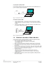
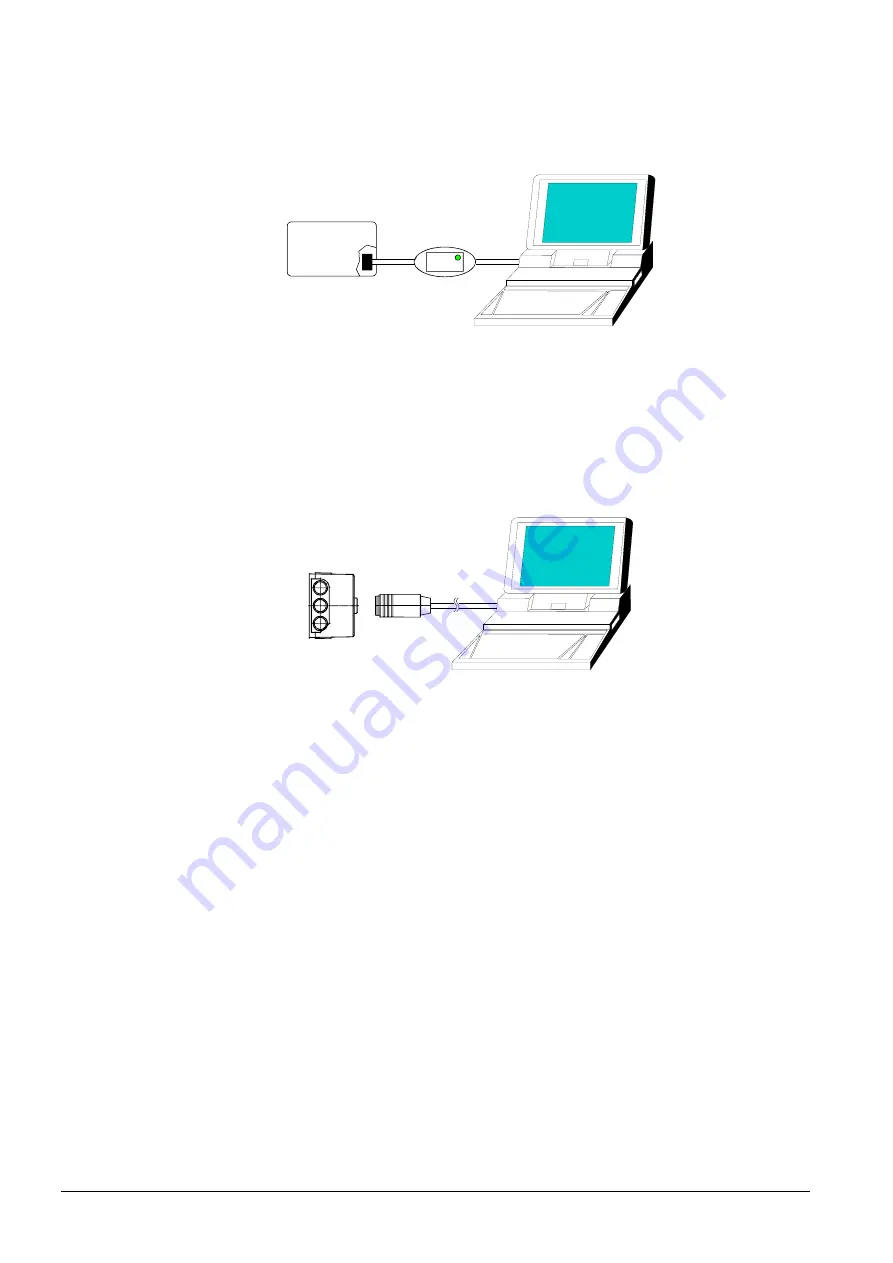
Connection BC interface OCI410
Connect the BC interface OCI410 without other extension with the USB interface at
your PC, follow the example design below.
ACS410
PC software
LME39...
OCI410
7106z181e/0708
RJ11
USB2.0
Figure 3: Connection BC interface OCI410
Connection interface OCI400...
Put the interface OCI400... in the connector at lockout reset button of LME39...
Interface diagnostics works only if the AGK20... lockout reset button extension is
not fitted
Connect the interface OCI400... without other extension to the interface at your
PC, follow the example design below
LME39...
OCI400
7106z182e/0708
ACS410
PC software
RS232
Figure 4: Connection interface OCI400...
1.6 Electrical
connection of flame detectors
It is important to achieve practically disturbance- and loss-free signal transmission:
Never run detector cables together with other cables
– Line capacitance reduces the magnitude of the flame signal
– Use a separate cable
Observe the permissible length of the detector cables (refer to Technical data)
The ionization probe and the ignition electrode are not protected against electric
shock hazard
Locate the ignition electrode and the ionization probe such that the ignition spark
cannot arc over to the ionization probe (risk of electrical overloads) and that it
cannot adversely affect the supervision of ionization
Insulation
resistance
– Must be a minimum of 50 M
between ionization probe and ground
– Soiled detector holders reduce the insulation resistance, thus supporting
creepage currents
Earth the burner in compliance with the relevant regulations; earthing the boiler
alone does not suffice


