Chapter 4 - Parameters and Menu Structure
Parameters (M3)
102 | 180
Siemens Industry, Inc.
Siemens BT300 HVAC Drive
DPD01809
Building Technologies
2016-06-07
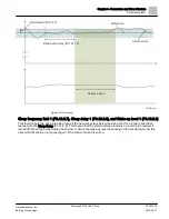
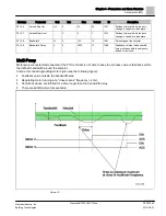
Criteria for disconnecting/removing motors:
●
Feedback value outside bandwidth area.
●
Regulating motor running at a “close-to-min” frequency (+2 Hz).
●
Conditions above are fulfilled for a time longer than the bandwidth delay
●
There are more motors running than the regulating one.
Interlock function (P3.14.2)
Interlocks can be used to tell the Multi Pump system that a motor is not available, for example, because the motor
is removed from the system for maintenance or bypassed for manual control.
Enable this function to use the interlocks. Choose the needed status for each motor by digital inputs (Interlock1
(P3.5.1.26) to Interlock 5 (P3.5.1.30). If the input is closed (TRUE) the motor is available for the Multi-Pump
system; otherwise, it will not be connected by the Multi-Pump logic.
Example of the Interlock logic:
If the motor starting order is
1
→
2
→
3
→
4
→
5
When the interlock of motor 3 is removed (the value of Interlock 3 (P3.5.1.28) is set to FALSE) the order changes
to:
1
→
2
→
4
→
5
If motor 3 is taken into use again (changing the value of Interlock 3 (P3.5.1.28) to TRUE), the system runs without
stopping and motor 3 is placed last in the sequence:
1
→
2
→
4
→
5
→
3
The next time the system is stopped or goes to sleep mode, the sequence returns to its original order.
1
→
2
→
3
→
4
→
5
Include FC (P3.14.3)
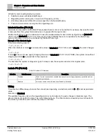
Table 69: Include FC Selections.
Selection
Selection name
Description
0
Disabled
Motor 1 (motor connected to variable frequency drive) is always frequency controlled and not
affected by interlocks.
1
Enabled
All motors can be controlled and are affected by interlocks.
Wiring
There are two different ways to make the connections depending on whether selection 0 or 1 is set as parameter
value.
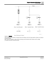
Selection 0, Disabled:
The variable frequency drive or the regulating motor is not included in the auto-change or interlocks logic. The
drive is directly connected to motor 1 as in the following figure. The other motors are auxiliary ones connected to
the mains by contactors and controlled by relays in the drive.
Summary of Contents for BT300 LonWorks
Page 1: ...Siemens BT300 HVAC Drive Operator s Manual DPD01809 Building Technologies 2016 06 07 ...
Page 8: ......
Page 179: ......


