Chapter 4 - Parameters and Menu Structure
Quick Setup (M1)
29 | 180
Siemens Industry, Inc.
Siemens BT300 HVAC Drive
DPD01809
Building Technologies
2016-06-07
Quick Setup (M1)
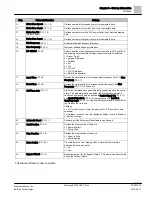
The Quick Setup parameter group is a collection of parameters that are the most commonly used during installation
and commissioning. They are collected in the first parameter group so that they can be found quickly and easily.
However, they can be also be reached and edited in the actual parameter groups. Changing a parameter value in
the Quick Setup group also changes the value of this parameter in its actual group.
The Quick Setup parameters are presented in the following table:
Table 4: Quick Setup Parameters.
Structure
Parameter
Unit
ID
Description
P1.1
Motor Nom Voltg
V
110
Defines nominal motor voltage from motor nameplate data.
Also see
Menu Structure P3.1.1.1.
P1.2
Motor Nom Freq
Hz
111
Defines nominal motor frequency from motor nameplate data.
Also see
Menu Structure P3.1.1.2.
P1.3
Motor Nom Speed
rpm
112
Defines nominal motor speed from motor nameplate data.
Also see
Menu Structure P3.1.1.3.
P1.4
Motor Nom Currnt
A
113
Defines nominal motor current from motor nameplate data.
Also see
Menu Structure P3.1.1.4.
P1.5
Motor Cos Phi
120
Defines nominal motor Cos Phi (power factor) from motor nameplate data.
Also see
Menu Structure P3.1.1.5.
P1.6
Motor Nom Power
hp
116
Defines nominal motor power from motor nameplate data.
Also see
Menu Structure P3.1.1.6.
P1.7
Current Limit
A
107
Defines maximum current limit for motor. Suggested to use Motor Nominal
Current (P1.4) multiplied by motor service factor from motor nameplate data.
Also see
Menu Structure P3.1.1.7.
P1.8
Min Frequency
Hz
101
Sets minimum motor frequency at which motor will run irrespective of
frequency setpoint.
Also see
Menu Structure P3.3.1.
P1.9
Max Frequency
Hz
102
Sets maximum motor frequency at which motor will run irrespective of
frequency setpoint.
Also see
Menu Structure P3.3.2.
P1.10
I/O A Ctrl Ref
117
Selects location of frequency setpoint source when in I/O A control. In the
following list of possible settings, the main setpoint is selected:
1= Preset Freq 0
2 = Keypad Reference
3 = Fieldbus
4 = AI1
5 = AI2
6 = AI1+AI2
7 = PID 1 Reference
8 = Motor Potentiometer
Also see
Menu Structure P3.3.3.
P1.11
Preset Freq 1
Hz
105
Used according to state of digital input defined for Preset Frequency
Selection 1 (P3.5.1.16). Decoding mode chosen with Preset Frequency Mode
(P3.3.10). Also see
Menu Structure P3.3.12.
P1.12
Preset Freq 2
Hz
106
Used according to state of digital inputs Preset Frequency Selection 2
(P3.5.1.17). Decoding mode chosen with Preset Frequency Mode (P3.3.10).
Also see
Menu Structure P3.3.13.
P1.13
Accel Time 1
s
103
Time allowed for motor to accelerate from a standstill (0) up to Maximum
Frequency (P1.9).
This parameter can also be found in Menu Structure P3.4.2
P1.14
Decel Time 1
s
104
Time allowed for motor to decelerate from Maximum Frequency (P1.9) to a
standstill (0). Also see
Menu Structure P3.4.3.
Summary of Contents for BT300 LonWorks
Page 1: ...Siemens BT300 HVAC Drive Operator s Manual DPD01809 Building Technologies 2016 06 07 ...
Page 8: ......
Page 179: ......


