background image


Chapter 4 - Parameters and Menu Structure 
Parameters (M3) 


36 | 180 
Siemens Industry, Inc. 

Siemens BT300 HVAC Drive 

DPD01809 

Building Technologies 


2016-06-07 


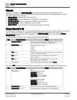
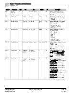
Basic Settings (M3.1.1) 

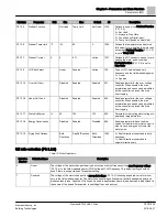
Table 14: Basic Motor Settings. 


Structure 

Parameter 

Unit 

Min 

Max 

Default 

ID 

Description 

P3.1.1.1 

Motor Nom Voltg 

Varies 

Varies 

Varies 

110 

Defines nominal motor voltage from 

motor nameplate data. 

Also see 

Menu Structure P1.1. 

P3.1.1.2 

Motor Nom Freq 

Hz 

320 

60 

111 

Defines nominal motor frequency 

from motor nameplate data. Also 

see 

Menu Structure P1.2. 

P3.1.1.3 

Motor Nom Speed 

rpm 

24 

19200 

Varies 

112 

Defines nominal motor speed from 

motor nameplate data. Also see 

Menu Structure P1.3. 

P3.1.1.4 

Motor Nom Currnt 

Varies 

Varies 

Varies 

113 

Defines nominal motor current from 

motor nameplate data. Also see 

Menu Structure P1.4. 

P3.1.1.5 

Motor Cos Phi 


0.3 

Varies 

120 

Defines nominal motor Cos Phi 

(power factor) from motor 

nameplate data. Also see 

Menu 

Structure P1.5. 

P3.1.1.6 

Motor Nom Power 

hp 

Varies 

Varies 

Varies 

116 

Defines nominal motor power from 

motor nameplate data. Also see 

Menu Structure P1.6. 

P3.1.1.7 

Current Limit 

Varies 

Varies 

Varies 

107 

Defines maximum current limit for 

motor. Suggested to use Motor 

Nominal Current (P3.1.1.4) 

multiplied by motor service factor 

from motor nameplate data.

 Also 

see 

Menu Structure P1.7. 

P3.1.1.8 

Motor Type 


IM 

PMM 

IM 

650 

Selection of the motor type as 

follows: 

0 = IM = Asynchronous Induction 

Motor 

1 = PMM = PM Synchronous Motor 

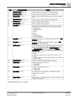
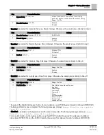
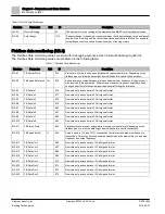
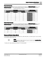
Motor Control Settings (M3.1.2) 

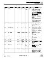
Table 15: Motor Control Settings. 


Structure 

Parameter 

Unit 

Min 

Max 

Default 

ID 

Description 

P3.1.2.1 

Switching Freq 

kHz 

1.5 

Varies 

Varies 

601 

Motor noise can be minimized using a 

high switching frequency. Increasing the 

switching frequency reduces the 

capacity of the drive. It is recommended 

to use a lower frequency when the motor 

cable is long in order to minimize 

capacitive currents in the cable. 

P3.1.2.2 

Motor Switch 


No 

Yes 

No 

653 

Prevents the drive from tripping when a 

motor switch is located between the 

drive and motor. 

0 = No 

1 = Yes 

P3.1.2.4 

Zero Freq Voltg 

40 

Varies 

606 

Defines the zero frequency voltage of 

the U/f curve. 

Summary of Contents for BT300 LonWorks

Page 1: ...Siemens BT300 HVAC Drive Operator s Manual DPD01809 Building Technologies 2016 06 07 ...

Page 2: ...port Programs that will ensure continuous trouble free system performance For further information contact your nearest Siemens Industry representative Copyright Siemens Industry Inc FCC Regulations The manual for an intentional or unintentional radiator shall caution the user that changes or modifications not expressly approved by the party responsible could void the user s authority to operate th...

Page 3: ...eader Your feedback is important to us If you have comments about this manual please submit them to SBT_technical editor us sbt siemens com Credits APOGEE is a registered trademark of Siemens Industry Inc Other product or company names mentioned herein may be the trademarks of their respective owners Printed in the USA ...

Page 4: ...Copyright Notice 4 180 Siemens Industry Inc Siemens BT300 HVAC Drive DPD01809 Building Technologies 2016 06 07 ...

Page 5: ...alog Output Terminal Connections 19 Analog Output 1 19 Digital Output Terminal Connections 20 Chapter 3 Start up Information 21 Procedure and Checklist 21 Commissioning Flowchart 21 Wizards 22 Startup Wizard P1 19 22 PID Mini Wizard P1 17 24 Multi Pump Wizard P1 18 25 Fire Mode Wizard P1 20 25 Bypass Wizard P1 21 26 Chapter 4 Parameters and Menu Structure 28 Quick Setup M1 29 Monitor Menu M2 30 Mu...

Page 6: ... 4 63 Fieldbus Data Mapping M3 6 66 Prohibited Frequencies M3 7 69 Limit supervisions M3 8 70 Protections M3 9 72 Automatic Reset M3 10 79 Timer Functions M3 11 81 Time Channels 81 Intervals 81 Timers 84 Example 84 PID Controller 1 M3 12 85 Basic Settings M3 12 1 85 Setpoints M3 12 2 86 Feedbacks M3 12 3 88 Feedforward M3 12 4 90 Process Supervision M3 12 5 91 Pressure Loss Compensation M3 12 6 92...

Page 7: ...5 8 116 Common Settings M5 8 1 117 N2 M5 8 3 118 BACnet MS TP M5 8 3 123 P1 FLN M5 8 3 131 Modbus RTU M5 8 3 136 Ethernet M 5 9 152 Common Settings M5 9 1 152 Modbus TCP M5 9 2 153 BACnet IP M5 9 3 158 User Settings M6 162 Parameter Backup M6 5 162 Parameter Compare M6 6 163 Favorites M7 163 User Levels M8 163 Chapter 5 Fault tracing 165 Fault Displays 165 Fault history 165 Fault codes 166 Chapter...

Page 8: ......

Page 9: ...ion of a step are designated with a Results which inform the user that a task was completed successfully are designated with a Composer software is properly installed A Valid license is available 1 Select Start Programs Siemens GMS Composer The Project Management window displays 2 Open an existing project or create a new one The project window displays Actions that should be performed are specifie...

Page 10: ...stantanément des blessures graves voir mortelles ou endommager l équipement WARNING Serious injury death or severe equipment damage could occur if a procedure or instruction is not followed as specified Le non respect d une procédure ou instruction peut provoquer des blessures graves voir mortelles ou endommager l équipement CAUTION Minor or moderate injury may occur if a procedure or instruction ...

Page 11: ...0 HVAC Drive and the user With the control keypad it is possible to control the speed of a motor to supervise the state of the equipment and to set the variable frequency driver s parameters Keypad Buttons The keypad features nine buttons used to configure and control the drive Figure 1 Keypad Buttons This button back reset allows you to move backwards in the menu backup a step when using a wizard...

Page 12: ...ad Stop Button P3 2 3 Keypad Display The keypad display indicates the status of the motor and the drive and any irregularities in motor or drive functions On the display you can view information about the present location in the menu structure and the item displayed See Chapter 4 for a comprehensive view of the menu structure Figure 2 Keypad Display Several pieces of information are available on t...

Page 13: ...d return to the previous level by pressing the Back Reset button Using the Keypad This section covers the editing of parameter values resetting of faults accessing the control page obtaining help related to parameters and configuring the items for the Favorites menu Editing Values NOTES 1 Some parameters cannot be changed when the drive is in the Run state 2 Some parameters require a power cycle t...

Page 14: ...ameter and select Reset Faults See Chapter 6 for further information on fault diagnostics Control Places A control place is the source of control where the drive can be started and stopped Every control place has its own parameter for selecting the frequency reference source In Hand the control place is the keypad by default The auto control place is determined by the setting in Auto Control Place...

Page 15: ...o available for faults alarms and the Start up Wizard Adding an Item to Favorites At times you may need to refer to certain parameter values or other items Instead of locating them one by one in the menu structure you can add them to a folder called Favorites where they can easily be reached To remove an item from Favorites see Favorites M7 163 in Chapter 4 NET Software Tool NET is a personal comp...

Page 16: ...order requirements for obtaining the desired protocols The RS 485 protocols are APOGEE P1 BACnet MS TP Johnson N2 and Modbus RTU The Ethernet protocols are BACnet IP and Modbus TCP The Echelon LonWorks protocol is available using an option card Part Number BT300 LONWORKS The built in RS 485 protocols are documented in section RS 485 in Chapter 4 The built in Ethernet protocols are documented in th...

Page 17: ...al Connections The control board terminals are located on the control module The control module is identical for all sizes of the BT300 HVAC Drive It contains the keypad terminals and the control processor of the drive Connect the control wiring to the BT300 control terminals per the site specific drawings Figure 3 Slot A Terminal Connections Figure 4 Slot B Terminal Connections ...

Page 18: ...o 10 Vdc signal 0V represents Minimum Frequency and 10V represents Maximum Frequency This scaling can be modified See the analog input parameters listed in Chapter 3 Analog Input 1 By default Analog Input 1 is configured for a 0 to 10 Vdc signal source The wiring is shown below See Figure 5 for the location of the AI1 DIP switch The DIP switch is set to the U voltage position at the factory AI1 Si...

Page 19: ...y set and digital inputs correctly configured before enabling them Digital Inputs 1 through 6 See Figure 5 for the location of the DIO DIP switch The DIP switch is set to the GND Grounded position at the factory Figure 8 Digital Input Terminal Connections Analog Output Terminal Connections The BT300 HVAC consists of one analog output built on Slot A When using the analog output the DIP switch must...

Page 20: ...ding Technologies 2016 06 07 Digital Output Terminal Connections The BT300 HVAC Drive consists of three digital relay outputs built on Slot B See Figure 5 for the location of the DIO DIP switch When using the digital outputs the DIP switch must be correctly set and digital outputs correctly configured Figure 10 Digital Output Terminal Connections ...

Page 21: ...This step should be completed on all drives at start up This will be automatically started at the end of the Factory Reset Select Quick Setup Startup Wizard P1 19 if necessary If any other wizards are needed select one of the following Quick Setup PID Mini Wizard M1 17 Quick Setup Multi Pump Wizard M1 20 Quick Setup Startup Wizard M1 19 Quick Setup Fire Mode Wizard M1 20 Quick Setup Bypass Wizard ...

Page 22: ...ly complete the Startup Wizard Step Parameter Question Settings 1 Language Selections P6 1 Select the icon for the language you want applied to the keypad This varies depending upon the language package installed 2 Daylight Saving P5 5 5 Select the Daylight Saving Rule 1 Off 2 EU 3 US 4 Russia 3 Time P5 5 2 Specify the current time of day in the following format hh mm ss where h hour m minute s se...

Page 23: ... Decel Time P3 4 3 Defines the time required to decrease output frequency from Max Frequency P3 3 1 to 0 frequency 19 Ctrl Place Auto P3 2 1 Start Stop commands are given differently depending upon the control place This parameter defines whether the Start Stop command is controlled by digital inputs as defined in Control Signal 1 A P3 5 1 1 and Control Signal 2 A P3 5 1 2 in accordance with the I...

Page 24: ...1 Source Selection P3 12 3 3 Several selections see P3 12 3 3 If one of the analog input signals is selected Step 6 displays Otherwise the wizard jumps directly to Step 7 Step Parameter Question Settings 6 Analog Input Signal Range 0 to 10V 0 to 20 mA 2 to 10V 4 to 20 mA 7 Error Inversion P3 12 1 8 Reverse Acting Direct Acting 8 Setpoint Source Selection P3 12 2 4 Several selections see P3 12 3 4 ...

Page 25: ...ese values are written down for future reference The Multi Pump Wizard is now complete Fire Mode Wizard P1 20 The Fire Mode feature of the drive is designed to place the drive in a mode that ignores all commands from the keypad fieldbuses and the personal computer tool In addition the drive will ignore all alarms and faults of the drive and continue providing frequency to the attached motor This i...

Page 26: ...dditional features can be enabled if desired The standard I O is re mapped for use with the Electronic Bypass option Additional parameters are available when the Electronic Bypass option is enabled The following steps are required to successfully complete the Bypass Wizard Step Parameter Question Settings 1 Select the Bypass P3 17 4 mode Electronic Conventional Disabled If Conventional is selected...

Page 27: ...erwise the wizard jumps directly to Step 9 Step Parameter Question Settings 8 Interlock Delay P3 2 12 Range 0 to 120 s 9 Auto Bypass P3 18 2 Enabled Disabled If Enabled is selected for Auto Bypass Step 10 displays Otherwise the wizard jumps directly to Step 11 Step Parameter Question Settings 10 Auto Bypass Delay P3 18 4 Range 0 to 30 s 11 Fault Selection P3 18 3 Select faults to enable auto Bypas...

Page 28: ... E M2 6 Multi Pump M5 5 Real Time Clock M2 8 Fieldbus Data M5 6 Power Unit Settings M2 9 Temp Inputs M5 7 Keypad Parameters M3 Parameters used for basic and advanced configuration requirements M3 1 Motor Settings M5 8 RS 485 M3 2 Start Stop Setup M5 8 1 Common Settings M3 3 References M5 8 3 BACnet MSTP1 M3 4 Ramps and Brakes M5 8 3 Modbus RTU1 M3 5 I O Config M5 8 3 N21 M3 5 1 Digital Inputs M5 8...

Page 29: ...rom motor nameplate data Also see Menu Structure P3 1 1 6 P1 7 Current Limit A 107 Defines maximum current limit for motor Suggested to use Motor Nominal Current P1 4 multiplied by motor service factor from motor nameplate data Also see Menu Structure P3 1 1 7 P1 8 Min Frequency Hz 101 Sets minimum motor frequency at which motor will run irrespective of frequency setpoint Also see Menu Structure P...

Page 30: ...on of the drive The PID Mini Wizard will precede this wizard P1 19 Startup Wizard 1171 Enable parameter for the Startup Wizard This wizard assist with the essential information required for drive operation This wizard is automatically enabled after Restore Factory Defaults P6 5 1 is activated P1 20 Fire Mode Wizard 1672 Enable parameter for the Fire Mode Wizard P1 21 Bypass Wizard 1823 Enable para...

Page 31: ...s the actual output frequency M2 2 2 FreqReference Hz 25 Displays the actual frequency reference setpoint M2 2 3 Motor Speed rpm 2 Displays the actual motor speed M2 2 4 Motor Current A 3 Displays the actual motor current M2 2 5 Motor Torque 4 Displays the calculated motor torque M2 2 7 Motor Power 5 Total power consumption of the drive in M2 2 8 Motor Power hp 73 Total power consumption of the dr...

Page 32: ... Active B8 Hand Control Active B9 PC Control Active B10 Preset Freq Active B12 FireMode Active B13 PreHeat Active M2 2 24 Appl StatusWord2 90 Bit coded application status word 2 B0 Acc Dec Prohibited B1 MotorSwitch Active M2 2 25 kWhTripCounter Low 1054 Energy counter with kWh output low word M2 2 26 kWhTripCounter High 1067 of times energy counter has spun around high word M2 2 27 Appl StatusWord...

Page 33: ... Varies 22 Error value of the PID controller for the attached motor M2 4 4 PID1 Output 23 Output of the PID controller for the attached motor M2 4 5 PID1 Status 24 0 Stopped 1 Running 3 Sleep Mode 4 In dead band PID Controller 2 Monitoring M2 5 The PID Controller 2 monitoring values are the actual values of the second PID controller which is used for external devices that require PID loop control ...

Page 34: ...ess data in 32 bit signed format M2 8 4 FB Data In 2 877 Raw value of process data in 32 bit signed format M2 8 5 FB Data In 3 878 Raw value of process data in 32 bit signed format M2 8 6 FB Data In 4 879 Raw value of process data in 32 bit signed format M2 8 7 FB Data In 5 880 Raw value of process data in 32 bit signed format M2 8 8 FB Data In 6 881 Raw value of process data in 32 bit signed form...

Page 35: ...ing parameter groups Table 13 Parameter Groups Menu and Parameter group Description Motor Settings M3 1 Basic and advanced motor settings Start Stop Setup M3 2 Start and stop functions References M3 3 Frequency references setup Ramps and Brakes M3 4 Acceleration and deceleration setup I O Config M3 5 Input Output I O configuration Fieldbus DataMap M3 6 Fieldbus data out setup Prohibited Freq 3 7 P...

Page 36: ...or Nom Power hp Varies Varies Varies 116 Defines nominal motor power from motor nameplate data Also see Menu Structure P1 6 P3 1 1 7 Current Limit A Varies Varies Varies 107 Defines maximum current limit for motor Suggested to use Motor Nominal Current P3 1 1 4 multiplied by motor service factor from motor nameplate data Also see Menu Structure P1 7 P3 1 1 8 Motor Type IM PMM IM 650 Selection of t...

Page 37: ...ameter for the over voltage controller When enabled the drive acceleration and speed can be modified by the controller to prevent the drive from tripping P3 1 2 17 StatorVoltAdjust 50 150 100 659 Parameter for adjusting stator voltage in permanent magnet motors P3 1 2 18 Energy Optimization Disabled Enabled Disabled 666 Enable parameter to have the drive search for the minimum motor current in ord...

Page 38: ...5 1 2 The functionality logic for these inputs is selected with I O A Start Stop Logic P3 2 6 The I O B Control Force P3 5 1 5 will determine when the Auto Control Place I O B is in use Auto Control Place I O B Start stop and reverse commands are controlled by two digital inputs chosen with Control Signal 1 B P3 5 1 3 and Control Signal 2 B P3 5 1 4 The functionality logic for these inputs is sele...

Page 39: ...lled with I O or fieldbus 1 Hand controlled with keypad P3 2 3 KeypadStopButton No Yes No 114 Defines the operational status of the keypad stop button as follows 0 No stop button is not functional in all control places 1 Yes stop button functions in all control places P3 2 4 Start Function Ramping Flying Start Varies 505 Defines the start function of the drive 0 Ramping Start 1 Flying Start P3 2 5...

Page 40: ... Mot InterlockTimeout s 0 120 0 1816 Defines the amount of time the drive will wait for the interlock feedback to be given before starting 0 No timeout time used Unit will wait indefinitely for the feedback before starting the drive 0 Unit will only wait this time for the feedback then start the drive P3 2 13 Run Interlock Proof 14060 Defines the run interlock proof timeout time If Run Interlock 1...

Page 41: ...3 Start Forward Ctrl Signal 2 B P3 5 1 4 Start Reverse 1 Ctrl Signal 1 A P3 5 1 1 Start Forward Edge Ctrl Signal 2 A P3 5 1 2 Start Reverse Edge Ctrl Signal 1 B P3 5 1 3 Inverted Stop Ctrl Signal 2 B P3 5 1 4 Inverted Stop 2 Ctrl Signal 1 A 3 5 1 1 Forward Edge Ctrl Signal 2 A 3 5 1 2 Backward Edge Ctrl Signal 1 B 3 5 1 3 Forward Edge Ctrl Signal 2 B 3 5 1 4 Backward Edge 3 Ctrl Signal 1 A P3 5 1 ...

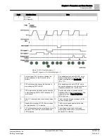
Page 42: ...n enable signal is set to TRUE which causes the frequency to rise towards the set frequency because CS1 is still active 3 CS1 is inactivated which causes the direction to start changing FWD to REV because CS2 is still active 10 Keypad stop button is pressed and the frequency fed to the motor drops to 0 This signal only works if KeypadStopButton P3 2 3 Yes 4 CS2 inactivates and the frequency fed to...

Page 43: ...se the Run enable signal has been set to TRUE 2 CS2 inactivates causing the frequency to drop to 0 7 Keypad stop button is pressed and the frequency fed to the motor drops to 0 This signal only works if KeypadStopButton P3 2 3 Yes 3 CS1 activates causing the output frequency to rise again The motor runs forward 8 CS1 activates causing the output frequency to rise again The motor runs forward 4 Run...

Page 44: ...ighest priority 8 Run enable signal is set to FALSE which drops the frequency to 0 The run enable signal is configured with RunEnable P3 5 1 11 3 CS1 is inactivated which causes the direction to start changing FWD to REV because CS2 is still active 9 Run enable signal is set to TRUE which unlike if value 0 is selected for this parameter has no effect because rising edge is required to start even i...

Page 45: ...which causes the frequency to rise towards the set frequency because CS1 is still active 3 CS2 is inactivated which causes the direction to start changing REV to FWD because CS1 is still active 9 Keypad stop button is pressed and the frequency fed to the motor drops to 0 This signal only works if KeypadStopButton P3 2 3 Yes 4 Also CS1 inactivates and the frequency drops to 0 10 The drive starts th...

Page 46: ...nable signal is configured with Run Enable P3 5 1 11 2 CS2 activates which causes the direction to start changing FWD to REV 8 Before a successful start can take place CS1 must be opened and closed again 3 CS2 is inactivated which causes the direction to start changing REV to FWD because CS1 is still active 9 Keypad stop button is pressed and the frequency fed to the motor drops to 0 This signal o...

Page 47: ...ce can be selected with Fieldbus Control Reference Selection P3 3 9 Table 26 Control Reference Settings Structure Parameter Unit Min Max Default ID Description P3 3 1 Min Frequency Hz 0 Parameter P3 3 2 0 101 Minimum allowed frequency reference P3 3 2 Max Frequency Hz Parameter P3 3 1 320 60 102 Maximum allowed frequency reference P3 3 3 I O A Ctrl Ref PresetFreq0 Motor Pot Ref AI1 AI2 117 Selects...

Page 48: ... 4 AI1 5 AI2 6 AI1 AI2 7 PID 1 Reference 8 Motor Potentiometer P3 3 10 PresetFreqMode Binary Coded Number of inputs Binary Coded 182 Defines the preset frequency mode to be used 0 Binary Coded 1 Number of inputs Preset freq selected according to number of digital inputs P3 3 11 Preset Freq 0 Hz Parameter P1 8 or P3 3 1 Parameter P1 9 or P3 3 2 5 180 Defines the frequency to be used when I O A Ctrl...

Page 49: ...be used when the following occurs 1 PresetFreqMode P3 3 10 is set to Binary Coded Preset Freq Sel0 P3 5 1 15 is activated Preset Freq Sel1 P 3 5 1 16 is activated Preset Freq Sel2 P3 5 1 17 is de activated 2 PresetFreqMode P3 3 10 is set to Number of Inputs Preset Freq Sel0 P3 5 1 15 is de activated Preset Freq Sel1 P3 5 1 16 is de activated Preset Freq Sel2 P3 5 1 17 is activated P3 3 15 Preset F...

Page 50: ...responses found in Protections P3 9 are defined for Alarm Preset Freq AI Low Fault P3 9 1 FieldbusComm Flt P3 9 19 P3 3 20 MotPot Ramp Time Hz s 0 1 500 10 331 Rate of change in the motor potentiometer reference when increased or decreased P3 3 21 MotPot Reset No Reset Powered down Stop State 367 Motor potentiometer frequency reference reset logic 0 No Reset 1 Reset if stop state 2 Reset if powere...

Page 51: ...Frequency 6 P3 3 17 On On On Preset Frequency 7 P3 3 18 Number of Inputs Operation The values of the preset frequencies are automatically limited between the Minimum Frequency P3 3 1 and Maximum Frequency P3 3 2 The following table displays the operation to select the preset frequencies Table 29 Number of Inputs Used Preset Frequencies 1 through 3 Required Action For use with 1 O Control Reference...

Page 52: ...ent A Varies Varies Varies 517 Defines the DC current to be used at start of the motor P3 4 9 DC Time Stop s 0 600 0 508 Determines if braking is ON or OFF and the braking time of the DC brake when the motor is stopping P3 4 10 DC Brake Current A Varies Varies Varies 507 Defines the current injected into the motor during DC braking 0 Disabled P3 4 11 DC BrakeFreqStop Hz 0 1 10 1 5 515 The output f...

Page 53: ... There are four I O configuration areas Digital Inputs Digital Outputs Analog Inputs and Analog Outputs Digital Inputs M3 5 1 The digital inputs are very flexible to use Parameters are functions features that are connected to the required digital input terminals The digital inputs are represented by the slot they exist on For example DigIN Slot A 2 means the second digital input on slot A basic I ...

Page 54: ...fines the location to determine when I O B Logic P3 2 7 should be followed Open Contact I O A Logic P3 2 6 is followed Contact Closure I O B Logic P3 2 7 is followed P3 5 1 6 I O B Ref Force DigIN Slot0 1 343 Defines the location to determine when I O B Ctrl Ref P3 3 4 should be followed Open Contact I O A Ctrl Ref P3 3 3 is followed Contact Closure I O B Ctrl Ref P3 3 4 is followed P3 5 1 7 Ext F...

Page 55: ...s P3 11 menu structure P3 5 1 20 Timer 3 DigIN Slot0 1 449 Defines the location to the rising edge to start timer 3 as programmed in Timer Functions P3 11 menu structure P3 5 1 21 Disable Timer Funct DigIN Slot0 1 1499 Enable parameter for all timer functions including Intervals 1 5 and Timer 1 3 programmable in Timer Functions P3 11 menu structure Contact closure Timer functions and reset timers ...

Page 56: ... 1 1618 Defines location of the reverse command when fire mode is active as defined by FireMode Activ Open P3 16 2 or FireMode Activ Close P3 16 3 Open Contact Forward Contact Closure Reverse NOTE This function has no effect in normal mode of operation Also see Menu Structure P3 16 6 P3 5 1 42 Keypad CTRL DigIN Slot0 1 410 Defines the location monitored to force the Control Place to Keypad P3 5 1 ...

Page 57: ...ignal Sel P3 5 2 1 When this parameter is given a value 0 the function that filters out disturbances from the incoming analog signal is activated NOTE Long filtering time makes the regulation response slower P3 5 2 3 AI1 Signal Range 0 10V 0 20 mA 2 10V 4 20 mA 0 10V 0 20 mA 379 Defines the signal range for the analog input defined by AI1 Signal Sel P3 5 2 1 Ranges are as follows 0 0 to 10 Vdc 0 t...

Page 58: ...141 Defines the location of the signal to be used as analog input 3 P3 5 2 14 AI3 Filter Time s 0 300 1 142 Defines the time it takes to reach 63 of a step change in the analog input signal defined by AI3 Signal Sel P3 5 2 13 P3 5 2 15 AI3 Signal Range 0 10V 0 20mA 2 10V 4 20mA 0 10V 0 20 mA 143 Defines the signal P3 5 2 13 Ranges are as follows 0 0 to 10 Vdc 0 to 20 mA 1 2 to 10 Vdc 4 to 20 mA NO...

Page 59: ...00 10V or 20 mA 0 P3 5 2 25 AI5 Signal Sel AnIN Slot0 1 188 Defines the location of the signal to be used as analog input 5 P3 5 2 26 AI5 Filter Time s 0 300 1 189 Defines the time it takes to reach 63 of a step change in the analog input signal defined by AI5 Signal Sel P3 5 2 25 P3 5 2 27 AI5 Signal Range 0 10V 0 20 mA 2 10V 4 20 mA 0 10V 0 20 mA 190 Defines the signal range for the analog input...

Page 60: ...ignal Inv Normal Inverted Normal 209 Defines the operation of the analog input 6 signal as follows Normal 0V or 0 mA 0 10V or 20 mA 100 Inverted 0V or 0 mA 100 10V or 20 mA 0 Digital Outputs M3 5 3 The digital relay outputs are very flexible to use Parameters are functions features that are connected to the required digital relay output terminals The digital outputs are configured by the slot they...

Page 61: ...te 2 Run The variable frequency drive operates motor is running 3 General fault A fault trip has occurred 4 General fault inverted A fault trip has not occurred 5 General alarm 6 Reversed The reverse command has been selected 7 At speed The output frequency has reached the set reference 8 Motor regulator activated One of the limit regulators for example current limit or torque limit is activated 9...

Page 62: ...en the drive is in Bypass mode 39 Bypass running Selects relay output terminal for Bypass contactor control 40 Drive active Selects relay output for the Drive active signal This signal is on when the drive is in Drive mode 41 Drive output contactor Controls the Drives Output contactor 42 Overload Fault Selects relay output for the Overload fault signal This signal is on when the Overload fault is ...

Page 63: ...ction None Remote Start None 13002 P3 5 3 4 3 RO3 Function None Remote Start None 13003 P3 5 3 4 4 RO4 Function None Remote Start None 13004 P3 5 3 4 5 RO5 Function None Remote Start None 13005 P3 5 3 4 6 RO6 Function None Remote Start None 13006 Slot E M3 5 3 5 If an expansion I O board that contains a digital relay output exists in slot E then this section will be populated with parameters to re...

Page 64: ...rack the Output Frequency based on 0 to Max Frequency P3 3 2 3 Freq Reference Track the Frequency Reference base on 0 to Max Frequency P3 3 2 4 Motor Speed Track the Motor Speed based on 0 to Motor Nom Speed P3 1 1 3 5 Output Current Track the Output Current based on 0 to Motor Nom Currnt P3 1 1 4 6 Motor Torque Track the Motor Torque based on 0 to TnMotor 7 Motor Power Track the Motor Power based...

Page 65: ... Vdc 0 mA 1 2 Vdc 4 mA P3 5 4 3 9 AO2 MinScale Varies Varies Varies 12058 Min Scale in process unit P3 5 4 3 10 AO2 MaxScale Varies Varies Varies 12059 Max Scale in process unit Slot D M3 5 4 4 If an expansion I O board that contains an analog output exists in slot C then this section will be populated with parameters to represent that I O Table 41 Analog Outputs Slot D Structure Parameter Unit Mi...

Page 66: ...4 5 5 AO1 MaxScale Varies Varies Varies 14054 Max Scale in process unit P3 5 4 5 6 AO2 Function 0 Test ProcessDataIn8 0 Test 14055 SeeTable AO Functions P3 5 4 5 7 AO2 Filter Time s 0 300 1 14056 Filter time of analog output signal 0 No filtering P3 5 4 5 8 AO2 Min Signal 0 Vdc 0 mA 2 Vdc 4 mA 0 Vdc 0 mA 14057 Settings 0 0 Vdc 0 mA 1 2 Vdc 4 mA P3 5 4 5 9 AO2 MinScale Varies Varies Varies 14058 Mi...

Page 67: ... FBDataOut 1 Sel P3 6 1 for further details BACnet AV_21 P1 Subpoint 51 P3 6 3 FB DataOut 3 Sel 0 35000 Current 45 854 Defines the data to be sent to the fieldbus as FB DataOut 3 Refer to FBDataOut 1 Sel P3 6 1 for further details BACnet AV_22 P1 Subpoint 52 P3 6 4 FB DataOut 4 Sel 0 35000 Torque 4 855 Defines the data to be sent to the fieldbus as FB DataOut 4 See FBDataOut 1 Sel P3 6 1 for furth...

Page 68: ... data to be sent to the fieldbus as FB DataOut 8 See FBDataOut 1 Sel P3 6 1 for further details BACnet AV_27 P1 Subpoint 57 P3 6 9 FB Run Enable Disabled Enabled Enabled 1829 Defines the run enable when in fieldbus control NOTE When fieldbus is not in use see Run Enable P3 5 1 11 For example to provide the PID1 Feedback over the fieldbus Complete the following Set Fieldbus Data Out 1 Selection P3 ...

Page 69: ...pTimeFactor P3 7 7 while within the range of this high limit and the Range 1 Low Lim P3 7 1 NOTE The drive will not control within these ranges it will either be faster or slower but never within the range defined P3 7 3 Range 2 Low Lim Hz 0 320 0 511 Defines the low limit of the second prohibited frequency See Range 1 Low Lim P3 7 1 for further details P3 7 4 Range 2 High Lim Hz 0 320 0 512 Defin...

Page 70: ...in the following table Table 45 Limit Supervisions Settings Structure Parameter Unit Min Max Default ID Description P3 8 1 Superv1 Item Output Frequency Analog Input 2 Output Frequency 1431 Defines the drive data to supervise for Superv1 Mode P3 8 2 in accordance with the Superv1 Limit P3 8 3 with deadband defined with Superv1 Hyst P3 8 4 0 Output Frequency 1 Frequency Reference 2 Motor Current 3 ...

Page 71: ... of supervision of the Superv2 Item P3 8 5 in accordance with the Superv2 Limit P3 8 7 with deadband defined with Superv2 Hyst P3 8 8 0 Not used 1 Low Limit Supervision 2 High Limit Supervision P3 8 7 Superv2 Limit Varies 200 200 25 1437 Defines the limit that Superv2 Item P2 8 5 is compared to which determines if Superv2 Mode P3 8 6 has occurred Unit of measure appears automatically P3 8 8 Superv...

Page 72: ...pport must be selected P3 9 4 Undervoltage Flt Fault Stored No History Fault Stored 727 Defines if the under voltage fault is stored in the fault history or not 0 Fault Stored 1 No History P3 9 5 OutputPhase Flt No Action Fault Coast Fault 702 Defines the response to an output phase loss Response settings are as follows 0 No Action 1 Alarm 2 Fault stop according to stop mode 3 Fault stop by coasti...

Page 73: ...4 This parameter gives the value for the min torque allowed when the output frequency is above the field weakening point P3 9 17 UL ZeroFreq Load 5 150 10 715 This parameter gives the value for the min torque allowed with zero frequency P3 9 18 UL Time Limit s 2 600 20 716 This is the maximum time allowed for an underload state to exist P3 9 19 FieldbusComm Flt No Action 4 Fault 733 Defines the re...

Page 74: ...lt Limit 30 200 155 742 Defines the temperature that TempFault Signal P3 9 25 must reach for triggering a fault P3 9 28 TempFault Response No Action Fault Coast Fault 740 Defines the response action when TempFault Signal P3 9 25 has past TempFault Limit P3 9 27 Response settings are as follows 0 No Action 1 Alarm 2 Fault stop according to stop mode 3 Fault stop by coasting P3 9 29 Run Interlock Fl...

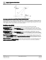
Page 75: ...e is set assuming that there is no external fan cooling the motor If an external fan is used this parameter can be set to 90 or even higher If you change Motor nominal current P3 1 1 4 this parameter is automatically restored to the default value Setting this parameter does not affect the maximum output current of the drive which is determined by Current Limit P3 1 1 7 alone The corner frequency f...

Page 76: ...be set shorter than that of the motor thermal protection The stall state is defined with two parameters Stall Current P3 9 12 and Stall Frequency Limit P3 9 14 If the current is higher than the set limit and the output frequency is lower than the set limit the stall state is true There is actually no real indication of the shaft rotation Stall protection is a type of over current protection Stall ...

Page 77: ...rip see Parameters of Stall Protection P3 9 11 Figure 21 Stall time count Under load protection P3 9 15 through P3 9 18 The motor under load protection ensures that there is load on the motor when the drive is running If the motor loses its load there might be a problem in the process for example a broken belt or a dry pump Motor under load protection can be adjusted by setting the under load curv...

Page 78: ... area load P3 9 16 The torque limit can be set between 10 0 and150 0 TnMotor This parameter gives the value for the minimum torque allowed when the output frequency is above the field weakening point See the following figure If you change Motor Nom Currnt P3 1 1 4 this parameter is automatically restored to the default value Figure 22 Setting of minimum load Under load protection Time limit P3 9 1...

Page 79: ...ion 0 Flying Start 1 According to Start Function P3 2 4 P3 10 3 Wait Time s 0 1 10000 30 717 Wait time before first reset is executed P3 10 4 Trial Time s 0 10000 330 718 When the trial time has elapsed and the fault is still active the drive will trip on fault P3 10 5 Number of Trials 1 10 10 759 Number of restart attempts irrespective of fault type P3 10 6 Undervoltage Flt No Yes Yes 720 Determi...

Page 80: ...rlock Flt No Yes No 14062 Determines if the Automatic Reset feature can reset when this fault occurs Automatic reset P3 10 1 Activate the Automatic reset after fault with this parameter NOTE Automatic reset is allowed for certain faults only By giving the parameters Undervoltage flt P3 10 6 to Wait Time P3 10 13 the value 0 or 1 you can either allow or deny the automatic reset after the respective...

Page 81: ...ram the closed and opened intervals of the input Time Channels The on off logic for the time channels is configured by assigning intervals and or timers to them One time channel can be controlled by many intervals or timers by assigning as many of these as needed to the time channel Intervals Every interval is given an ON Time and OFF Time This is the daily time that the interval will be active du...

Page 82: ...el defined in AssignToChannel P3 11 1 5 on the day of week defined in From Day P3 11 1 3 to and including day defined in To Day P3 11 1 4 P3 11 1 3 From Day Sunday Saturday 1466 From Day Defines the beginning day of the week the ON Time P3 11 1 1 and OFF Time P3 11 1 2 are issued to the unit 0 Sunday 1 Monday 2 Tuesday 3 Wednesday 4 Thursday 5 Friday 6 Saturday P3 11 1 4 To Day Sunday Saturday 146...

Page 83: ...11 1 3 P3 11 3 4 To Day Sunday Saturday Sunday 1477 See description for P3 11 1 4 P3 11 3 5 AssignToChannel Not Used Time Channel 3 Not Used 1478 See description for P3 11 1 5 Interval 4 M3 11 4 Table 50 Interval 4 Structure Parameter Unit Min Max Default ID Description P3 11 4 1 ON Time hh mm ss 0 00 00 23 59 59 0 00 00 1479 See description for P3 11 1 1 P3 11 4 2 OFF Time hh mm ss 0 00 00 23 59 ...

Page 84: ...ime channel 1 3 for the timer 0 Not used 1 Time Channel 1 2 Time Channel 2 3 Time Channel 3 Timer 2 M3 11 7 Table 53 Timer 2 Structure Parameter Unit Min Max Default ID Description P3 11 7 1 Duration s 0 72000 0 1491 See description for P3 11 6 1 P3 11 7 2 AssignToChannel Not Used Time Channel 3 Not Used 1492 See description for P3 11 6 2 Timer 3 M3 11 8 Table 54 Timer 3 Structure Parameter Unit M...

Page 85: ...a value of Time Channel 1 3 Timer 1 used for the override operation outside of normal office hours Set Duration P3 11 6 1 to a value of 1800 30 minutes Set Assign to Channel P3 11 6 2 to a value of Time Channel 1 Set Timer 1 P3 5 1 18 to a value of DigIN Slot A 1 4 Control Source location of the start stop Set Control Signal 1 A P3 5 1 1 to a value of TimeChannel 1 PID Controller 1 M3 12 The PID C...

Page 86: ...ies Varies 0 1056 Defines the dead band area around the setpoint in process units The PID output is locked if the feedback stays within the dead band area for the Dead Band Delay P3 12 1 10 P3 12 1 10 Dead Band Delay s 0 320 0 1057 Defines the time for dead band Table 56 Process Units Selection Unit Unit Unit Unit 0 10 kg h 20 kW 30 ft3 h 1 1 min 11 m3 s 21 C 31 in wg 2 rpm 12 m3 min 22 gal s 32 f...

Page 87: ...ies 0 1018 Defines the level for the PID feedback value wake up supervision P3 12 2 10 SP 1 Boost x 2 2 1 1071 Setpoint can be boosted with a digital input P3 12 2 11 SP 2 Source Not Used Test Sequence Keypad SP2 431 See description for SP 1 Source P3 12 2 4 P3 12 2 12 SP 2 Minimum 200 200 0 1073 Minimum value of Setpoint at Analog Signal Minimum P3 12 2 13 SP 2 Maximum 200 200 100 1074 Maximum va...

Page 88: ...taIn8 17 Test Sequence Feedbacks M3 12 3 Table 59 Feedback Structure Parameter Unit Min Max Default ID Description P3 12 3 1 Function Source1 Mean Source1 333 Settings 1 Only Source 1 in use 2 SQRT Source1 Flow ConstantxSQRT Pressure 3 SQRT Source1 Source2 4 SQRT Source1 SQRT Source2 5 Source1 Source2 6 Source1 Source2 7 Min Source1 Source2 8 Max Source1 Source2 9 Mean Source1 Source2 P3 12 3 2 Ga...

Page 89: ...t Analog Signal Minimum P3 12 3 8 FB 2 Maximum 200 200 100 339 Maximum value at Analog Signal Maximum Table 60 Feedback Sources Settings Description 0 Not Used Setpoint is not used 1 AI1 Use analog input 1 2 AI2 Use analog input 2 3 AI3 Use analog input 3 4 AI4 Use analog input 4 5 AI5 Use analog input 5 6 AI6 Use analog input 6 7 ProcessDataIn1 Use ProcessDataIn1 8 ProcessDataIn2 Use ProcessDataI...

Page 90: ... P3 12 4 1 P3 12 4 3 FF 1 Source Not Used ProcessDataIn8 Not Used 1061 Settings 0 Not used 1 AI1 2 AI2 3 AI3 4 AI4 5 AI5 6 AI6 7 ProcessDataIn1 8 ProcessDataIn2 9 ProcessDataIn3 10 ProcessDataIn4 11 ProcessDataIn5 12 ProcessDataIn6 13 ProcessDataIn7 14 ProcessDataIn8 AIs and ProcessDataIn are handled as and scaled according to feedback min and max NOTE ProcessDataIn settings use two decimal places...

Page 91: ...eter Unit Min Max Default ID Description P3 12 5 1 Enable Superv Disabled Enabled Disabled 735 Settings 0 Disabled 1 Enabled P3 12 5 2 Upper Limit Varies Varies Varies Varies 736 Upper actual process value supervision P3 12 5 3 Lower Limit Varies Varies Varies Varies 758 Lower actual process value supervision P3 12 5 4 Delay s 0 30000 0 737 If the desired value is not reached within this time a fa...

Page 92: ...utput Frequency M2 2 1 Min Frequency P3 3 1 Max Frequency P3 3 2 Min Frequency P3 3 1 P3 12 6 3 Enable SP 2 Varies Disabled Enabled Disabled 1191 Enables the drive to raise or lower the setpoint depending on output frequency SP 2 Max Comp P3 12 6 2 is the compensation at maximum frequency This can be used with incorrectly placed sensors For example if a pressure sensor is placed far away from the ...

Page 93: ...he drive into sleep mode if the frequency stays below the sleep limit for a longer period than that set with the Sleep Delay P3 12 2 8 This means that the start command remains on but the run request is turned off When the actual value goes below or above the wake up level depending on the set acting mode the drive will activate the run request again if the start command is still on 11105 emf Dead...

Page 94: ...rectly affecting the controlled process value Example You are controlling the water level of a tank by means of flow control The desired water level has been defined as a setpoint and the actual level as feedback The control signal acts on the incoming flow Think of the outflow as a disturbance that can be measured Based on the measurements of the disturbance you can try to compensate for this dis...

Page 95: ...wer limits around the reference are set When the actual value goes above or below a counter starts counting up towards the Delay P3 12 5 4 When the actual value is within the allowed area the same counter counts down instead Whenever the counter is higher than the Delay an alarm or fault depending on the selected response is generated 11108 emf Regulating mode Upper limit P3 12 5 2 Lower limit P3 ...

Page 96: ...fter the pump This will give the right pressure directly after the pump but farther down in the pipe the pressure will drop depending on the flow Enable Setpoint 1 P3 12 6 1 and Setpoint 1 max compensation P3 12 6 2 The sensor is placed in Position 1 The pressure in the pipe will remain constant when we have no flow However with flow the pressure will drop farther down in the pipe This can be comp...

Page 97: ...lding Technologies 2016 06 07 Figure 30 Enable Setpoint 1 for Pressure Loss Compensation PID Controller 2 M3 13 The PID Controller 2 settings configure the second PID controller which controls an external device The PID Controller 2 consists of the following settings Basic Settings Setpoints Feedback Process Supervision ...

Page 98: ...ProcessUnitMax Varies Varies Varies 100 1665 Defines the maximum of the range for the process unit P3 13 1 9 ProcessUnitDeci 0 4 2 1666 Defines the number of positions after the decimal place that is to be displayed P3 13 1 10 Error Inversion Normal Inverted Normal 1636 Defines the action of the PID loop 0 Reverse Acting Fdbk Stpt Increase PID Output 1 Direct Acting Fdbk Stpt Decrease PID Output P...

Page 99: ...ximum Feedback M3 13 3 Table 66 PID Controller 2 Feedback Structure Parameter Unit Min Max Default ID Description P3 13 3 1 Function Source1 Mean Source1 1650 Settings 1 Only Source 1 in use 2 SQRT Source1 Flow ConstantxSQRT Pressure 3 SQRT Source1 Source2 4 SQRT Source1 SQRT Source2 5 Source1 Source2 6 Source1 Source2 7 Min Source1 Source2 8 Max Source1 Source2 9 Mean Source1 Source2 P3 13 3 2 Ga...

Page 100: ...hich the motors are started to guarantee their equal wear The controlling motor can be included in the Auto Change and interlock logic or it may be selected to always function as Motor 1 Motors can be taken out of use momentarily for example for service This is completed using the interlock function The Multi Pump settings are presented in the following table Table 68 Multi pump Settings Structure...

Page 101: ...dwidth 0 100 10 1097 Percentage of the setpoint P3 14 9 Bandwidth Delay s 0 3600 10 1098 Feedback outside the bandwidth time must pass before pumps are added or removed Multi Pump Motors are connected disconnected if the PID controller is not able to keep the process value or feedback within the defined bandwidth around the setpoint Criteria for connecting adding motors also see the following figu...

Page 102: ...motor starting order is 1 2 3 4 5 When the interlock of motor 3 is removed the value of Interlock 3 P3 5 1 28 is set to FALSE the order changes to 1 2 4 5 If motor 3 is taken into use again changing the value of Interlock 3 P3 5 1 28 to TRUE the system runs without stopping and motor 3 is placed last in the sequence 1 2 4 5 3 The next time the system is stopped or goes to sleep mode the sequence r...

Page 103: ... 06 07 Figure 32 Multi pump FC Disabled Selection 1 Enabled If the regulating motor needs to be included in the auto change or interlock logic make the connection according to the following figure Each motor is controlled by a relay but the contact logic ensures that the first connected motor is always connected to the drive and near the mains ...

Page 104: ...Chapter 4 Parameters and Menu Structure Parameters M3 104 180 Siemens Industry Inc Siemens BT300 HVAC Drive DPD01809 Building Technologies 2016 06 07 Figure 33 Multi pump FC Enabled ...

Page 105: ...e postponed until all conditions are met this is to avoid for example sudden pressure drops while the system is performing an auto change when there is a high capacity demand at a pump station Example In the auto change sequence after the auto change has taken place the motor with the highest priority is placed last and the others are moved up by one place Starting order priority of motors 1 2 3 4...

Page 106: ...de Activ Close P3 16 3 P3 16 2 FireMode Activ Open DigIN Slot0 2 1596 Defines location of fire mode activation on contact opening Open Contact Fire Mode Active Contact Closure No Action Also see Menu Structure P3 5 1 39 P3 16 3 FireMode Activ Close DigIN Slot0 1 1597 Defines location of Fire Mode activation on contact closing Open Contact No Action Contact Closure Fire Mode Active Also see Menu St...

Page 107: ...4 1 Preset Speeds 2 Keypad 3 Fieldbus 4 AI1 5 AI2 6 AI1 AI2 7 PID1 8 Motor Potentiometer P3 16 6 FireMode Reverse DigIN Slot0 1 1618 Defines location of the reverse command when Fire Mode is active as defined by FireMode Activ Open P3 16 2 or FireMode Activ Close P3 16 3 Open Contact Forward Contact Closure Reverse NOTE This function has no effect in normal mode of operation Also see Menu Structur...

Page 108: ...C F Selection ºC ºF ºF 1197 Defines the selection of the unit s temperature type parameters Selectable for Celsius or Fahrenheit P3 17 4 ByPass Disabled Electronic Disabled 1809 Defines the bypass option connected to the drive NOTE To set the proper value for this parameter it is not recommended to change this parameter This parameter is set during the run of the Bypass Wizard P1 21 Possible setti...

Page 109: ...y to the motor Motor will spin at full speed P3 18 3 AutoByp Faults 1812 Defines the authorized faults for the Auto Bypass feature to activate P3 18 4 AutoBypass Delay s 1 30 1 1817 Defines the delay time from when the drive faults and the bypass is enabled P3 18 5 EssentServEnable Disabled Enabled Disabled 1826 Enables parameter to the Essential Services feature If enabled when activated by Essen...

Page 110: ... reset the drive from the fault condition NOTES 1 Remove external control signal before resetting the fault to prevent unintentional restart of the drive 2 The fault remains active until it is cleared with one of the following methods If a fieldbus communication is in use command the Reset Fault object If a digital input is programmed for Fault Reset Close P3 5 1 9 or Fault Reset Open P3 5 1 10 to...

Page 111: ... hours minutes NOTE This is not resettable See Operating Time P4 7 3 for resettable version M4 6 7 Run Time y d hh mm 2293 Displays the motor run time in years days hours minutes M4 6 11 Power On Time y d hh mm Displays the power on time in years days hours minutes M4 6 15 Start Cmd Counter 2295 Displays the number of times the power unit has been started Trip Counters M4 7 Trip Counters contain t...

Page 112: ...nd Slot B Slot C M5 2 Provides status of I O found on Slot C Slot D M5 3 Provides status of I O found on Slot D Slot E M5 4 Provides status of I O found on Slot E Real Time Clock M5 5 Configuration and status of the real time clock Power Unit Settings M5 6 Configuration and status of the fan and sine filter Keypad M5 7 Configuration of keypad specific information RS 485 M5 8 Configuration and stat...

Page 113: ...gnal M5 1 15 Relay Output 3 OFF ON 2516 Status of Relay Output 3 Signal Slot C M5 2 Displays the status of the available I O for the option card installed in Slot C The available parameters change depending upon the option card installed See the I O Option Board Type B User s Manual DPD01158 for a list of available option cards and their I O types Table 80 I O Slot C Structure Parameter Min Max De...

Page 114: ...ption board M5 2 4 2 Board Status Displays status of the option board Real time clock M5 5 Table 83 Real Time Clock Settings Structure Parameter Unit Min Max Default ID Description M5 5 1 Battery State Not Installed Change Battery Installed 2205 Status of battery 1 Not installed 2 Installed 3 Change Battery M5 5 2 Time hh mm ss 2201 Current time of day M5 5 3 Date dd mm 2202 Current date M5 5 4 Ye...

Page 115: ...etime M5 6 1 5 Sine Filter M5 6 4 Sine filter support restricts overmodulation depth and prevents thermal management functions from decreasing switching frequency Table 85 Sine Filter Settings Structure Parameter Unit Min Max Default ID Description P5 6 4 1 Sine Filter Disabled Enabled Disabled 2527 Enable parameter for the Sine Filter Keypad M5 7 Configuration of the keypad specific items such as...

Page 116: ... page when Default Page P5 7 2 is set to a value of Enter Menu Index For example if Output Frequency M2 2 1 is to be displayed set this parameter to a value of 2 2 1 0 0 P5 7 4 Contrast 30 70 50 830 Set the contrast of the display P5 7 5 Backlight Time min 0 60 5 818 Defines the amount of time of keypad inactivity that must occur before the backlight of the display turns off 0 backlight always ON ...

Page 117: ... Building Technologies 2016 06 07 Figure 34 Connecting the RS 485 Cable If the Siemens BT300 HVAC Drive is the last device on the bus the bus termination may be required See the figure below for enabling to bus termination Figure 35 Bus Termination Common Settings M5 8 1 Common settings are presented in the following table ...

Page 118: ... over a 4 000 foot distance running at 9 600 bps Logically the N2 is a master slave protocol the supervisory controller is normally the master Data is partitioned into common HVAC control objects such as analog input analog output binary input and binary output N2 messaging supports the reading writing and overriding of these points Additionally there are messages defined to perform uploads and do...

Page 119: ...d format as follows B0 Start Stop B2 Fault Reset M5 8 3 2 7 Status Word 2405 Displays the status word in a bit coded format as follows N2 Point Map Analog Inputs AI All analog inputs AI points have the following features Support Change of State COS reporting based on high and low warning limits Support Change of State COS reporting based on high and low alarm limits Support Change of State COS rep...

Page 120: ...AI 17 FBProcessDataOut2 0 decimal places V 18 FBProcessDataOut3 0 decimal places V 19 FBProcessDataOut4 0 decimal places AI 20 FBProcessDataOut5 0 decimal places AI 21 FBProcessDataOut6 0 decimal places AI 22 FBProcessDataOut7 0 decimal places AI 23 FBProcessDataOut8 0 decimal places Binary Inputs BI All binary inputs BI points have the following features Support Change of State COS reporting base...

Page 121: ...he variable an acknowledge response is given and the value will be internally clamped to its limit Table 92 N2 Analog Outputs NPT NPA Description Units Note AO 1 Comms Speed 2 decimal places AO 2 Current Limit A 2 decimal places AO 3 Minimum Speed Hz 2 decimal places AO 4 Maximum Speed Hz 2 decimal places AO 5 Accel Time s 1 decimal place AO 6 Decel Time s 1 decimal place AO 7 FBProcessDataIn1 2 d...

Page 122: ...able 94 Internal Integers NPT NPA Description Units ADI 1 Active Fault Code ADI 2 Control Word ADI 3 Status Word ADI 4 Any Parameter ID N2 Protocol Quick Setup For monitoring of objects using the N2 protocol complete the following changes 1 Select Main Menu I O and Hardware M5 RS 485 M5 8 Common Settings M5 8 1 Protocol P5 8 1 1 Edit 2 Select N2 from the list and press the button 3 Select Main Men...

Page 123: ...l as well as utilizing BACnet protocol to communicate between systems BACnet is an internationally accepted protocol for building automation and control over a communications network BACnet provide a method by which computer based control equipment form different manufacturers can work together or interoperate To achieve components must be able to exchange and understand BACnet data messages The S...

Page 124: ...ual Instance 2395 Displays the actual device BACnet instance number M5 8 3 2 4 Fault Code 2396 None Baud Rate Fault Displays the fieldbus communications fault status as follows 0 None 1 Sole Master 2 Duplicated MAC ID 3 Baud Rate Fault M5 8 3 2 5 Control Word 2397 Displays the control word in a bit coded format as follows B0 Start Stop B2 Fault Reset M5 8 3 2 6 Status Word 2398 Displays the status...

Page 125: ...Object Name Description Active Inactive Text PV Access Menu BI_0 DI1 STATUS Status of digital input 1 signal ON OFF R M5 1 1 BI_1 DI2 STATUS Status of digital input 2 signal ON OFF R M5 1 2 BI_2 DI3 STATUS Status of digital input 3 signal ON OFF R M5 1 3 BI_3 DI4 STATUS Status of digital input 4 signal ON OFF R M5 1 4 BI_4 DI5 STATUS Status of digital input 5 signal ON OFF R M5 1 5 BI_5 DI6 STATUS...

Page 126: ... This object is the command of the state for Relay Output 1 ON OFF C FB ControlWord B13 BO_1 RO2 CMD This object is the command of the state for Relay Output 2 ON OFF C FB ControlWord B14 BO_2 RO3 CMD This object is the command of the state for Relay Output 3 ON OFF C FB ControlWord B15 BO_3 RUN ENABLE Run Enable ENABLE DISABL C BO_4 CMD RUN STOP Run Stop Command RUN STOP C FB ControlWord B0 BO_5 ...

Page 127: ...nk Temperature DEG R M2 2 11 AV_16 ACTIVE FAULT Active Fault Code R M2 2 18 AV_17 LAST FAULT 1 Most recent fault R AV_18 LAST FAULT 2 Second most recent fault R AV_19 LAST FAULT 3 Third most recent fault R AV_20 FBDATAOUT 01 Fieldbus Process Data Out 1 R P3 6 1 AV_21 FBDATAOUT 02 Fieldbus Process Data Out 2 R P3 6 2 AV_22 FBDATAOUT 03 Fieldbus Process Data Out 3 R P3 6 3 AV_23 FBDATAOUT 04 Fieldbu...

Page 128: ...P3 1 1 4 AV_46 MTRNOM POWER Motor Nominal Power HP W P3 1 1 6 AV_47 MTRNOM SPEED Motor Nominal Speed rpm W P3 1 1 3 AV_48 MTRNOM VLTG Motor Nominal Voltage V W P3 1 1 1 AV_49 MTRNOM FREQ Motor Nominal Frequency Hz W P3 1 1 2 AV_50 MOTOR COSPHI Motor COSPHI W P3 1 1 5 AV_51 BYPASS Bypass Type R P3 17 4 AV_52 BYP SAFESTAT Bypass Safety Status R AV_53 BYP RUN TIME Bypass Run Time R AV_54 PID1 GAIN R ...

Page 129: ...ult regardless of the control source FAULT NOFLT R BV_5 ALARM STATUS Status of Alarm regardless of the control source ALARM NORMAL R BV_6 AT ZERO Motor is running at Zero speed TRUE FALSE R BV_7 AT SETPOINT Motor is running at Setpoint TRUE FALSE R BV_8 RO1 STATUS Status of relay output 1 ON OFF R P5 1 13 BV_9 RO2 STATUS Status of relay output 2 ON OFF R P5 1 14 BV_10 RO3 STATUS Status of relay ou...

Page 130: ... Reference ON OFF C BV_32 INTERLOCK 1 Run Interlock 1 ON OFF R P3 5 1 12 BV_33 INTERLOCK 2 Run Interlock 2 ON OFF R P3 5 1 13 BV_34 ENERGY OPT Energy Optimization ON OFF R P3 1 2 18 BV_35 AUTO RESET Auto Reset ON OFF R P3 10 1 BV_36 FIREMODESTAT Fire Mode Active ACTIVE INACTV R BV_37 BYP ACTIVE ACTIVE INACTV R BV_38 BYP RUNNING YES NO R BV_39 REM SAFETY 1 FAULT NOFLT R BV_40 REM SAFETY 2 FAULT NOF...

Page 131: ...busCTRL 3 Set FieldbusCtrl Ref P3 3 9 to a value of AI1 or AI2 depending upon which AI is in use For commanding Start Stop through a Digital Input and Speed Reference through the BACnet MS TP protocol complete the following steps 1 Complete all settings required for Monitoring as listed above 2 Set Ctrl Place Auto P3 2 1 to a value of I O Control 3 Set I O A Ctrl Ref P3 3 3 to a value of Fieldbus ...

Page 132: ... messages are sent to device number 99 and all devices on the network respond to this address therefore address 99 is a reserved address and cannot be used on any device on the network P5 8 3 1 2 Baud Rate 2535 bps 4800 9600 4800 Defines the communications speed on the network which must match all devices on the network Possible settings are 1 4800 2 9600 P5 8 3 1 3 Communications Timeout 2536 s 0...

Page 133: ...SPEED 0 RPM 1 0 M2 2 3 13 LAI TORQUE 0 0 1 0 M2 2 5 14 LAI VOLTAGE 0 V 0 1 0 M2 2 9 15 LAI FIREMODESTAT 0 1 0 P3 16 7 16 LAI DRIVE KWH 0 KWH 0 1 0 P4 4 1 17 LAI DRIVE MWH 0 MWH 0 1 0 P4 4 1 18 LAI RUN TIME 0 HRS 10 0 P4 4 7 20 LAO OVRD TIME 1 HRS 1 0 21 LDO RUN ENABLE STOP ENABLE STOP P3 5 1 11 22 LDO CMD FWD REV FWD REV FWD 23 LDI FWD REV FWD REV FWD 24 LDO CMD RUN STOP STOP RUN STOP 25 LDI RUN S...

Page 134: ...1 0 1 0 P3 6 1 51 LAI FBDATA OUT 2 0 1 0 P3 6 2 52 LAI FBDATA OUT 3 0 1 0 P3 6 3 53 LAI FBDATA OUT 4 0 1 0 P3 6 4 54 LAI FBDATA OUT 5 0 1 0 P3 6 5 55 LAI FBDATA OUT 6 0 1 0 P3 6 6 56 LAI FBDATA OUT 7 0 1 0 P3 6 7 57 LAI FBDATA OUT 8 0 1 0 P3 6 8 58 LAO PID1 GAIN 1000 00 PCT 0 1 0 P3 12 1 1 59 LAO PID1 I TIME 10 SEC 0 1 0 P3 12 1 2 60 LAO PID1 D TIME 0 SEC 0 1 0 P3 12 1 3 61 LAI PID1 STATUS 0 1 0 M...

Page 135: ...LAI MOTOR N PWR HP 0 134 0 P3 1 1 6 88 LAI MOTOR N SPD RPM 1 24 P3 1 1 3 89 LAI MOTOR N VOLT VOLTS 1 0 P3 1 1 1 90 LAI MOTOR N FREQ HZ 0 01 8 P3 1 1 2 91 LDI FAULT ACTIVE NO Yes No 92 LAI FAULT ID 0 1 0 M2 2 18 93 LDO RESET FAULT 1 0 RESET NORMAL 94 LAI BYP ENABLE 1 0 P3 17 4 95 LAI BYP SAFESTAT 0 1 0 M2 2 28 96 LDI BYP ACTIVE OFF ON OFF 97 LDI BYP RUNNING OFF ON OFF 98 LAI BYP RUN TIME 0 HRS 1 0 ...

Page 136: ...omplete the following steps 1 Complete all settings required for Monitoring as listed above 2 Set Ctrl Place Auto P3 2 1 to a value of I O Control 3 Set I O A Ctrl Ref P3 3 3 to a value of Fieldbus Modbus RTU M5 8 3 Modbus RS 485 Parameters and Monitoring Values Table 106 Parameters Related with Modbus Used through RTU Structure Parameter Unit Min Max Default ID Description Parameters P5 8 3 1 1 S...

Page 137: ...d M5 8 3 2 2 Comm Status 0 99 999 0 0 2382 Displays the fieldbus protocol status as follows 0 Initializing Protocol is starting 1 Stopped Protocol is stopped 2 Operational Protocol is communicating 3 Faulted see Last Fault M5 8 3 2 4 for detail 4 Inactive No communications has occurred M5 8 3 2 3 Illegal Functions 2383 Format xx yyy where xx indicates bad frames and yyy indicates good messages M5 ...

Page 138: ...d received from the fieldbus Based on 32 bits as described below B0 Start Stop 0 Stop 1 Start B1 Direction 0 Forward 1 Reverse B2 Fault Reset 0 No action 1 Reset faults B3 B31 Not used M5 8 3 2 11 Status Word 2391 Displays the status word sent to the fieldbus Based on 32 bits as described below B0 Ready 0 Not Ready 1 Ready B1 Run 0 Stopped 1 Running B2 Direction 0 Forward 1 Reverse B3 Fault 0 No f...

Page 139: ...drive has received The Communication status includes a common error counter that counts CRC and parity errors and a counter for good messages Only messages to the current slave in use are counted in the good messages This parameter displays as xx yyy where xx indicates bad frames and yyy indicates good messages For example 01 002 would represent one bad frame and two good messages Illegal function...

Page 140: ...sage Coil 127 decimal is addressed as Coil 007E hex 126 decimal Holding register 40001 is addressed as register 0000 in the data address field of the message The function code field already specifies a holding register operation Therefore the 4XXXX reference is implicit Holding register 40108 is addressed as register 006B hex 107 decimal Modbus Memory Map The Siemens variables and fault codes as w...

Page 141: ...formation see Control word bits in this chapter Table 110 Defined Modbus Coil Registers Address Function Purpose 0001 RUN STOP Control Word bit 0 0002 Direction Control Word bit 1 0003 Fault reset Control Word bit 2 Discrete inputs Input discrete registers contain binary data Read For more information see Status word bits in this chapter Table 111 Defined Modbus Discrete Inputs Address Function Pu...

Page 142: ...ounter 16 bit Resettable Operation Day Counter 146 40201 40203 Energy counter 16bit Energy Counter 147 40301 40303 Resettable energy counter 16 bit Resettable Energy Counter 147 40401 40430 Fault history 16 bit Fault History 147 Application IDs Application IDs are parameters that depend on the frequency converter s application These parameters can be read and written by pointing the corresponding ...

Page 143: ...tatus Word are formed of 32 bits Only the initial 16 bits can be read in the 16 bit area Control word bits The Control word is composed of 32 bits The bits are described in the following table Unused bits must be set to zero Table 115 Control Word Bits Bit Name Value 1 Value 0 Description B0 Start Stop Start request Stop request Start Stop command to application B1 Direction Reverse Forward Comman...

Page 144: ...Running Stop Indicates whether the drive is running or stopped B2 Direction Counterclockwise Clockwise Indicates the rotation direction of the motor B3 Fault Faulted Not faulted Indicates if a fault is active B4 Alarm Alarm No alarm Indicates if an alarm is active B5 AtReference True False Reference frequency reached B6 ZeroSpeed True False Motor running at zero speed B7 FluxReady True False Motor...

Page 145: ...arameter value can be read and written in the address 10601 and so on Table 119 ID Map Initialization Once the IDMap address range has been initialized with any parameter ID number the parameter value can be read and written in the IDMap Read Write address range address IDMap address 100 Table 120 Parameter Values in 16 bit IDMap Read Write Registers Address Data 410601 Data included in parameter ...

Page 146: ...n Day Counter Address Register Purpose 40001 440001 Years 40002 440002 Days 40003 440003 Hours 40004 440004 Minutes 40005 440005 Seconds Resettable Operation Day Counter Reset the counter by writing 1 for Parameter ID2311 Table 123 Resettable Operation Day Counter Address Register Purpose 40101 440101 Years 40102 440102 Days 40103 440103 Hours 40104 440104 Minutes 40105 440105 Seconds Energy Count...

Page 147: ...ter ID2312 Table 125 Resettable Energy Counter Address Register Purpose 40301 440301 Energy 40302 440302 Format 40303 440303 Unit 1 kWh 2 MWh 3 GWh 4 TWh Fault history The fault history can be viewed by reading from address 40401 onward The faults are listed in chronological order so that the latest fault is mentioned first and the oldest last The fault history can contain 29 faults at the same ti...

Page 148: ...6 Data HI 00 hex Data 1 0001 hex 1 Setting control word run bit to 1 Data LO 01 hex Data HI 00 hex Data 2 0000 hex 0 Data LO 00 hex Data HI 13 hex Data 3 1388 hex 5000 Speed Reference to 50 00 Data LO 88 hex ERROR CRC HI C8 hex CRC field C8CB hex 51403 CHECK CRC LO CB hex Message frame 01 10 07 D0 00 03 06 00 01 00 00 13 88 C8 CB The reply to Preset Multiple Registers message is the echo of the 6 ...

Page 149: ...ead Input Registers message contains the values of the read registers Answer Slave Master ADDRESS 01 hex Slave address 1 hex 1 FUNCTION 04 hex Function 4 hex 4 DATA Byte count 04 hex Byte count 4 hex 4 Data HI 13 hex Speed reference 1388 hex 5000 50 00 Data LO 88 hex Data HI 09 hex Output Frequency 09C4 hex 2500 25 00 Hz Data LO C4 hex ERROR CRC HI 78 hexCRC field 78E9 hex 30953 CHECK CRC LO hex R...

Page 150: ...ilure ERROR CRC HI 42 hex CRC field 42C3 hex 17091 CHECK CRC LO C3 hex Reply frame 01 84 04 42 C3 Quick Setup For monitoring of objects using ModBus RTU complete the following steps 1 Select Main Menu I O and Hardware M5 RS 485 M5 8 Common settings M5 8 1 Protocol Edit 2 Select ModBus RTU 3 Select Main Menu I O and Hardware M5 RS 485 M5 8 ModBus RTU M5 8 3 Parameters M5 8 3 1 Slave Address M5 8 3 ...

Page 151: ...opbits M5 8 3 1 4 Edit 10 Select desired stop bits For commanding of Run Stop using ModBus RTU complete the following steps in addition to the Monitoring steps above 1 Select Main Menu Quick Setup M1 Ctrl Place Auto M1 15 Edit 2 Select FieldBusCTRL For commanding of Speed Reference using ModBus RTU complete the following steps in addition to the monitoring steps above 1 Select Main Menu Quick Setu...

Page 152: ...tings M5 9 1 Table 127 Ethernet Common Settings M5 9 1 Structure Parameter Min Max Unit Default ID Description P5 9 1 1 IP Address Mode DHCP with AutoIP Fixed IP DHCP with AutoIP 2482 Defines the IP addressing mode as follows 0 Fixed IP 1 DHCP with AutoIP P5 9 1 2 Fixed IP See below P5 9 1 3 IP Address 2483 Displays the actual IP Address in use P5 9 1 4 Subnet Mask 2484 Displays the actual subnet ...

Page 153: ...ices connecting to local network This address is valid for a certain period of time If no DHCP server is found an automatic random IP is given A fixed IP address is specified manually and does not change When the mode is changed from DHCP to Fixed the addresses will read IP 192 168 0 10 Subnet mask 255 255 0 0 Default gateway 192 168 0 1 IP address P5 9 1 3 An IP address is a series of numbers as ...

Page 154: ...ions 0 2451 See Illegal functions P5 9 2 2 1 3 M5 9 2 2 1 4 Illegal data addresses 0 2452 See Illegal data addresses P5 9 2 2 1 4 M5 9 2 2 1 5 Illegal data values 0 2453 See Illegal data values P5 9 2 2 1 5 M5 9 2 2 1 6 Slave device busy 0 2454 See Slave device busy P5 9 2 2 1 6 M5 9 2 2 1 7 Memory parity error 0 2455 See Memory parity error P5 9 2 2 1 7 M5 9 2 2 1 8 Slave device failure 0 2456 Se...

Page 155: ...on errors M5 9 2 2 1 3 Illegal functions 0 2473 See Illegal functions P5 9 2 2 1 3 M5 9 2 2 1 4 Illegal data addresses 0 2474 See Illegal data addresses P5 9 2 2 1 4 Only displays after a connection has been established Modbus TCP Settings Common Settings Connection limit P5 9 2 1 1 Defines how many clients can access the server simultaneously Unit identifier number P5 9 2 1 2 The Modbus slave add...

Page 156: ...is value counts error situations The data address received in the query refers to an invalid address for the server or slave This corresponds to Modbus fault code 02h Illegal data values P5 9 2 2 1 5 This value counts error situations A value contained in the query data field refers to an invalid value for server or slave This corresponds to Modbus fault code 03h Slave device busy P5 9 2 2 1 6 Thi...

Page 157: ...enu I O and Hardware M5 Ethernet M5 9 Common settings M5 9 1 IP Address Mode M5 9 1 1 2 Verify this is set to DHCP with AutoIP 3 Select Main Menu I O and Hardware M5 Ethernet M5 9 Common settings M5 9 1 IP Address M5 9 1 2 4 Verify that a valid IP Address has been assigned If using a Fixed IP address complete the following 1 Select Main Menu I O and Hardware M5 Ethernet M5 9 Common settings M5 9 1...

Page 158: ...te the following steps in addition to the Monitoring steps above 1 Select Main Menu Quick Setup M1 Ctrl Place Auto M1 15 Edit 2 Select FieldBusCTRL For commanding of Speed Reference using BACnet IP complete the following steps in addition to the monitoring steps above 1 Select Main Menu Quick Setup M1 I O A Ctrl Ref M1 10 Edit 2 Select Fieldbus BACnet IP M5 9 3 BACnet IP Parameters and Monitoring ...

Page 159: ...rotocol status 1 3 1 Stopped 2 Operational 3 Faulted M5 9 3 2 2 Communication status 0 0 99 999 0 0 0 99 Number of messages with errors 0 999 Number of messages without communication errors M5 9 3 2 3 Actual instance number 0 65535 Serial number Shows actual Device Object s instance number M5 9 3 2 4 Control word hex See IP monitoring values M5 9 3 2 5 Status word hex See IP monitoring values BACn...

Page 160: ...eter can be used if the master is periodically polling the slaves Protocol in use P5 9 3 1 3 Use this parameter to enable and disable the BACnet IP protocol When the parameter value is set to 1 the BACnet IP protocol is enabled When the parameter value is set to 0 the BACnet IP protocol is disabled IP Monitoring Values Fieldbus protocol status P5 9 3 2 1 Fieldbus protocol status tells the status o...

Page 161: ...lete the following steps 1 Select Main Menu I O and Hardware M5 Ethernet M5 9 Common settings M5 9 1 IP Address Mode M5 9 1 1 Edit 2 Select Fixed IP 3 Select Main Menu I O and Hardware M5 Ethernet M5 9 Common settings M5 9 1 IP Address M5 9 1 2 Edit 4 Enter the desired IP address 5 Select Main Menu I O and Hardware M5 Ethernet M5 9 Common settings M5 9 1 Subnet Mask M5 9 1 3 Edit 6 Enter the desir...

Page 162: ... keypad specific settings This section contains the following information Table 134 User Settings Menu and Parameter Group Description Language Selection P6 1 Selection of the language the keypad is displayed in Parameter Backup M6 5 Backup and restore functions for the drive Parameter Compare M6 6 Parameter comparison to defaults or backup files Drive Name P6 7 User defined name for the drive Use...

Page 163: ...e sets Table 136 Parameter Compare M6 6 Structure Parameter ID Description P6 6 1 Active Set Set 1 2493 Initiates a compare of the drive s active parameter set to the saved set 1 All parameters that are different are displayed with values P6 6 2 Active Set Set 2 2494 Initiates a compare of the drive s active parameter set to the saved set 2 All parameters that are different are displayed with valu...

Page 164: ...e complete the following steps 1 Set User Level P8 1 to a value of Normal 2 When prompted for Access Code P8 2 enter the value previously entered when locking the key pad Table 137 User Level Settings Structure Parameter Unit Min Max Default ID Description P8 1 User Level Normal Monitoring Normal 1194 Defines the user level mode of the keypad 0 Normal All menus are available 1 Monitoring Only the ...

Page 165: ... the parameter group Protections The fault can be reset with the Reset button on the control keypad or via the I O terminal The faults are stored in the Fault history menu which can be browsed Fault codes are outlined in the following table NOTE For a fault condition contact Technical Support Always write down all texts and codes on the keypad display and a description of the problem together with...

Page 166: ...igh over voltage spikes in supply Start Stop sequence too fast Make deceleration time longer Activate overvoltage controller Check input voltage 11 Over voltage software fault 3 20 Earth fault hardware fault Current measurement has detected that the sum of motor phase current is not zero insulation failure in cables or motor Check motor cables and motor 21 Earth fault software fault 5 40 Charging ...

Page 167: ...ss has failed For example retain variables could not be restored 610 Necessary device properties cannot be read 647 Software error Update the software Should the fault re occur contact your distributor 648 Invalid function block used in application System software and application are not compatible 649 Resource overload Error when loading parameter initial values Error when restoring parameters Er...

Page 168: ...nd stop the drive Load the software and start the drive 30 500 Safety Configuration Appears when safety configuration switch has been installed Remove the safety configuration switch from the control board 501 Safety Configuration Too many STO option boards have been detected in the drive only one is supported Remove the extra STO option boards 502 Safety Configuration STO option board has been in...

Page 169: ...encoder 1 channels are missing 423 Encoder reversed 424 Encoder board missing 44 430 Device changed different type Option board changed for one not present in the same slot before No parameter settings are saved Reet the option board parameters 45 440 Device changed different type Option board added The option board was not previously present in the same slot No parameter settings are saved Reset ...

Page 170: ... of the digital input as defined by Remote Safety 5 P3 5 1 48 1580 Remote Safety 6 Verify the status of the digital input as defined by Remote Safety 6 P3 5 1 49 1680 Remote Safety 7 Verify the status of the digital input as defined by Remote Safety 7 P3 5 1 50 1780 Remote Safety 8 Verify the status of the digital input as defined by Remote Safety 8 P3 5 1 51 81 1081 Overload Overload Relay has tr...

Page 171: ...rs 171 180 Siemens Industry Inc Siemens BT300 HVAC Drive DPD01809 Building Technologies 2016 06 07 Chapter 6 Technical Information This chapter provides general technical information for the BT300 Variable Frequency Drive Product Numbers Figure 37 ...

Page 172: ...016 06 07 Power Ratings The following chart shows the BT300 HVAC Drive power ratings in accordance with frame sizes Interpreting Serial Numbers and Date Codes Each BT300 HVAC Drive has a manufacturing serial number The date code is part of the serial number The following example shows how to interpret the date code and serial number ...

Page 173: ... 100 000 AIC Frequency Reference Analog Input Keypad Resolution 0 01 to 0 1 10 bit accuracy 1 Resolution 0 01 Hz Field weakening point 8 to 320 Hz Acceleration time 0 1 to 3000 0 seconds Deceleration time 0 1 to 3000 0 seconds Ambient Operating Temperature 14 F 10 C no frost to 104 F 40 C up to 122 F 50 C with derating Relative Humidity 0 to 95 rh non condensing non corrosive Air quality Chemical ...

Page 174: ... 45 56 FS5 57 65 FS6 63 72 FS7 43 73 FS8 58 73 FS9 54 75 Heatsink cooling fan output FS4 49 CFM FS5 88 CFM FS6 219 CFM FS7 159 CFM FS8 426 CFM FS9 560 CFM Agency Approvals Conformity UL 508C UL cUL CE BTL RoHS compliant EN61800 5 1 2007 Country Of Origin COO United States of America Control Method Linear parabolic and programmable V f and flux current control low power mode Control I O Analog Inpu...

Page 175: ...overload protection Motor stall protection Motor underload protection Short circuit protection of 10 Vdc and 24 Vdc reference voltages Control Board Technical Specifications Table 140 Control Module Technical Specifications Terminal Signal Description Specification Slot A 1 10 Vdc Reference Output 3 Maximum current 10 mA 2 Analog Input 1 Signal 0 through 10 Vdc or 0 through 20 mA selection with DI...

Page 176: ...3 Relay Output 1 Normally Open 24 Relay Output 2 Normally Closed Switching capacity 24 Vdc 8A 250 Vac 8A 125 Vdc 0 4A Minimum switch load 5 Vdc 0 mA 25 Relay Output 2 Common 25 Relay Output 2 Normally Open 32 Relay Output 2 Common Switching capacity 24 Vdc 8A 250 Vac 8A 125 Vdc 0 4A Minimum switch load 5 Vdc 0 mA 33 Relay Output 2 Normally Open Fieldbus Technical Data APOGEE P1 BACnet MS TP Modbus...

Page 177: ...300 CVR 21 FS5 BT300 CVR 21 FS6 NEMA 1 Gland Plate BT300 EDPLT N1 FS4 BT300 EDPLT N1 FS5 BT300 EDPLT N1 FS6 Accessory Description Frame Size 7 8 8 NEMA 1 to NEMA 12 Upgrade NEMA 12 Cover BT300 CVR 2154 FS7 BT300 CVR 2154 FS8 N A NEMA 12 Gland Plate N A N A N A Internal Fan for s n C1407xxxx and earlier BT300 INTFAN FS7 BT300 INTFAN FS8 BT300 INTFAN FS9 Internal Fan for s n C1408xxxx and later Acce...

Page 178: ...mistor input and two relay outputs BT300 OPT B4 V Option board with one analog input and two analog outputs BT300 OPT B5 V Option board with three relay outputs BT300 OPT B9 V Option board with five digital inputs and one relay output BT300 OPT BF V Option board with one analog output one digital output and one relay output BT300 OPT BH V Option board with three analog inputs for PT100 PT1000 NI 1...

Page 179: ......

Page 180: ...ision 1000 Deerfield Pkwy Buffalo Grove IL 60089 1 847 215 1000 Siemens Industry Inc 2016 Technical specifications and availability subject to change without notice Document ID DPD01809 DPD01809B Siemens BT300 HVAC Drive Edition 2016 06 07 Operator s Manual ...

Reviews: