Semiconductor Group
4-55
1998-04-01
Instruction Set
C500 Family
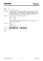
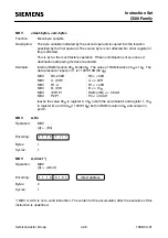
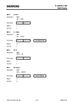
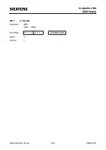
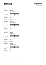
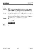
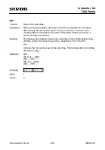
MOVX
<dest-byte>, <src-byte>
Function:
Move external
Description:
The MOVX instructions transfer data between the accumulator and a byte of
external data memory, hence the ÒXÓ appended to MOV. There are two types of
instructions, differing in whether they provide an eight bit or sixteen-bit indirect
address to the external data RAM.
In the first type, the contents of R0 or R1 in the current register bank provide an
eight-bit address multiplexed with data on P0. Eight bits are sufficient for external
l/O expansion decoding or a relatively small RAM array. For somewhat larger
arrays, any output port pins can be used to output higher-order address bits. These
pins would be controlled by an output instruction preceding the MOVX.
In the second type of MOVX instructions, the data pointer generates a sixteen-bit
address. P2 outputs the high-order eight address bits (the contents of DPH) while
P0 multiplexes the low-order eight bits (DPL) with data. The P2 special function
register retains its previous contents while the P2 output buffers are emining the
contents of DPH. This form is faster and more efficient when accessing very large
data arrays (up to 64 Kbyte), since no additional instructions are needed to set up
the output ports.
It is possible in some situations to mix the two MOVX types. A large RAM array with
its high-order address lines driven by P2 can be addressed via the data pointer, or
with code to output high-order address bits to P2 followed by a MOVX instruction
using R0 or R1.
Example:
An external 256-byte RAM using multiplexed address/data lines is connected to the
C500 port 0. Port 3 provides control lines for the external RAM. Ports 1 and 2 are
used for normal l/O. Registers 0 and 1 contain 12H and 34H. Location 34H of the
external RAM holds the value 56H. The instruction sequence
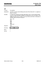
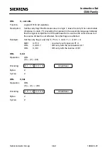
MOVX
A, @R1
MOVX
@R0,A
copies the value 56H into both the accumulator and external RAM location 12H.

