CPU Functions
C500 Family
Semiconductor Group
2-1
1998-04-01
2
CPU Architecture
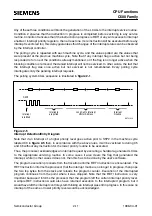
The typical architecture of a C500 family microcontroller is shown in
includes all main functional blocks of the C500 microcontrollers. The shaded blocks are basic
functional units which are mandatory for each C500 microcontroller. The other functional blocks
such as XRAM, peripheral units, and ROM/RAM sizes are specific to each C500 microcontroller
derivative.
Figure 2-1
C500 Microcontroller Architecture Block Diagram
The core block represents the CPU (Central Processing Unit) of the C500 family microcontrollers.
The CPU consists of the instruction decoder, the arithmetic section, the CPU registers, and the
program control section. The housekeeper unit generates internal signals for controlling the
functions of the individual internal units within the microcontroller. Port 0 and port 2 are required for
accessing external code and data memory and for emulation purposes. The external control signals
and the clock generation are handled in the external control block. The access control unit is
responsible for the selection of the on-chip memory resources. The IRAM provides the internal RAM
which includes the general purpose registers. The interrupt requests from the peripheral units are
handled by an interrupt controller unit.
C500 device specific is the configuration of the on-chip peripheral units. Serial interfaces, timers,
capture/compare units, A/D converters, watchdog units, or a multiply/divide unit are typical
examples for on-chip peripheral units. The external signals of these peripheral units are available
at multifunctional parallel I/O ports or at dedicated pins.
MCB02769
RST
EA
PSEN
ALE
XTAL
Ext.
Control
Access
Control
ROM
XRAM
Housekeeper
C500 Core
(1 or 8 Datapointer)
IRAM
Interrupt
Controller
Serial
Port
Timers
WDU
MDU
Control
Parallel
Port
Peripheral
Bus
Basic functional blocks
Address Bus
Data Bus
Port0/Port2
A
D
Port
Parallel


