background image

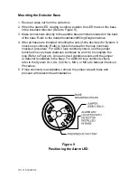
Mounting the Detector Base

1. Route all wires out from the outlet box.

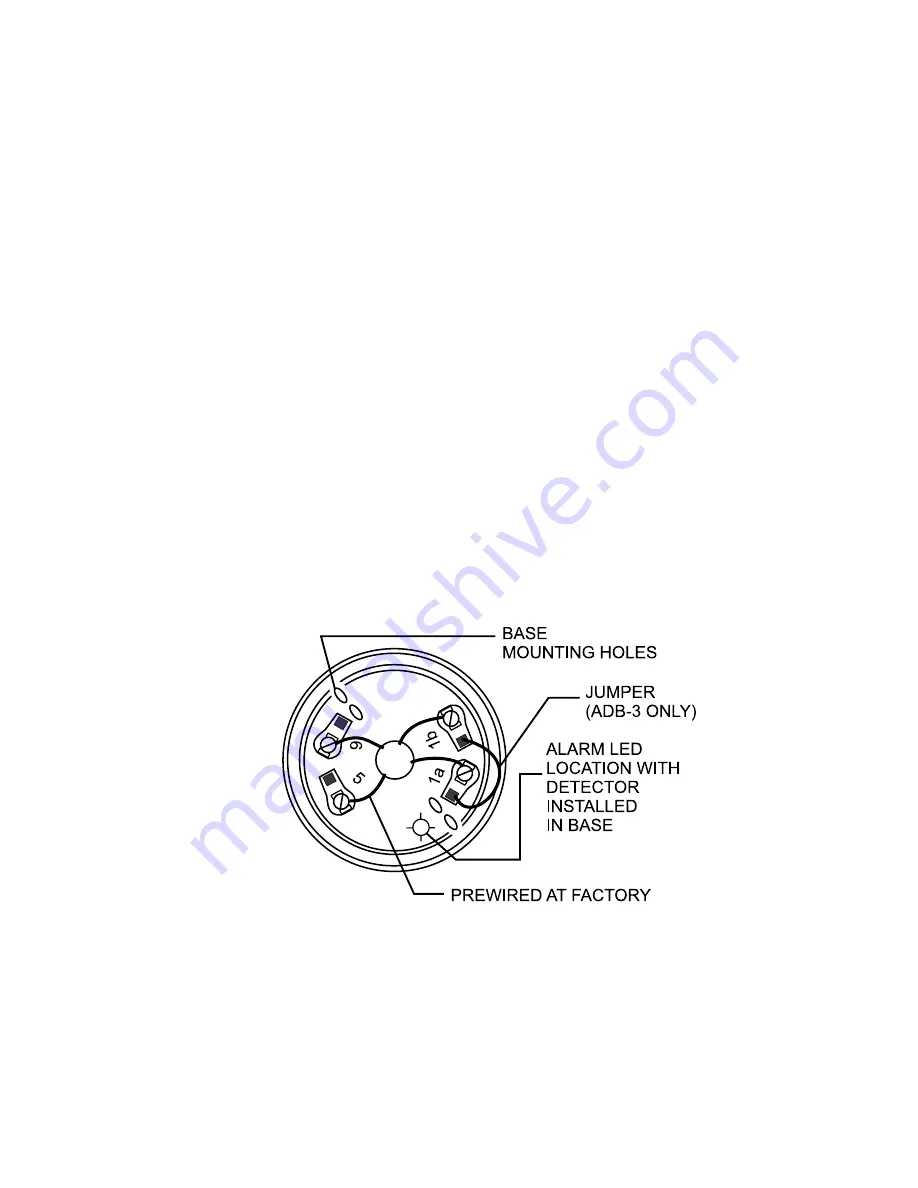
2. When the alarm LED viewing is critical, position the LED mark on the base

in the intended direction (Refer to Figure 9).

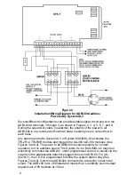
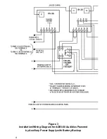
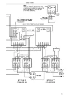
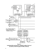
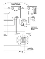
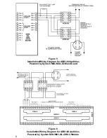
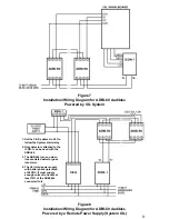
3. Make connections directly to the audible base terminals located on the back

of the base. Refer to the related lnstallation/Wiring Diagram above.

4. After all bases are installed, including the end-of-line device(s) for System 3,

check loop continuity. Refer to System manual for the loop continuity
checkout procedure. For ADB-3 loop continuity check, use the jumper
furnished in every base (between terminals 1a and 1b) to complete the
loop (Refer to Figure 9). An open circuit condition exists until the jumper
or detector is installed in the base. For ADBI-60 loop continuity check,
refer to the System XL3, IXL (ICON-1), MXL, or MXL-IQ Manual Checkout
Procedure.

Figure 9

Positioning the Alarm LED

P/N 315-086238-5

5. If loop continuity is acceptable, remove the jumper at each base and

proceed with detector head installation.

Summary of Contents for CERBERUS PYROTRONICS ADB-3

Page 1: ... East Pearce Street Richmond Hill Ontario L4B 1B7 CN CAUTION The ADB 3 must not be used as the primary evacuation system but only as a supplemental device CAUTION Do not use looped wire under Terminal 5 of DB 3S base Use a break in the wire at the terminal to provide supervision of connection Model ADBI 60 The CERBERUS PYROTRONICSTM Model ADBI 60 Audible Base consists of a standard Series 3 base c...

Page 2: ...0U modules See Figures 3 and 4 The power to all ADBI 60s reverses polarity for normal operation but no audibles sound The System XL3 or MXL MXL IQ may then selectively command the ADBI 60 under programmed control to sound via the circuitry in the addressable detector plugged into each ADBI 60 For IXL ICON 1 the CE S is programmed to follow the system alarm relay See Figures 7 and 8 Only those ADBI...

Page 3: ...or the compatibility details of INX ALD and audible circuit wiring 2 Maximum line resistance permitted both wires not including the end of line resistor is 3 ohms A minimum of 14 AWG wire must be used 3 T tapping of the audible circuit Figures 2 3 4 5 and 6 is not allowed 4 If the ADBI 60 is powered by System XL3 Figure 2 the total System power available for indicating appliances is 5A If more tha...

Page 4: ...4 Figure 3 Installation Wiring Diagram for ADBI 60 Audibles Powered by Auxiliary Power Supply with Battery Backup ...

Page 5: ...5 ...

Page 6: ...6 Figure 4 Installation Wiring Diagram for ADBI 60 Audibles Powered by Auxiliary Power Supply No Battery Backup ...

Page 7: ...7 ...

Page 8: ...8 Figure 5 Installation Wiring Diagram for ADBI 60 Audibles Powered by System MXL MXL IQ Main Board Figure 6 Installation Wiring Diagram for ADBI 60 Audibles Powered by System MXL MXL IQ CSM 4 Module ...

Page 9: ...upply System IXL 1 Set the CE S address to 201 to follow the System alarm relay 2 Only detectors attached to the ICON 1 can be used with the ADBI 60 3 The ADBI 60 turns on when its associated detector goes into alarm 4 The UL listed power supply with battery backup is rated at 24 VDC It must supply enough current to handle at least 10 of the ADBI 60s connected to it ...

Page 10: ...l Fire Alarm Code Chapter 5 and CAN ULC S524 as a guide or starting point if practical in a detector installation layout This spacing is based on ideal conditions smooth ceiling no air movement and no physi cal obstructions In all installations except in special circumstances like computer room underfloors locate the detector on the ceiling a minimum of 6 inches from a side wall or on a wall betwe...

Page 11: ... DT 3P P N 315 084401 5 PE 3 P N 315 090875 6 PE 3T P N 315 090875 6 in the InstallationlWiring Diagrams above and wired to the specific system modules and control panels following the appropriate instructions For opera tion with System XL3 and System MXL MXL IQ note any limitations on the number of audible bases permitted on each AA 30U AE 30U SPX 1 MMB 1 2 SMB 1 2 or CSM 4 audible circuit depend...

Page 12: ... s for System 3 check loop continuity Refer to System manual for the loop continuity checkout procedure For ADB 3 loop continuity check use the jumper furnished in every base between terminals 1a and 1b to complete the loop Refer to Figure 9 An open circuit condition exists until the jumper or detector is installed in the base For ADBI 60 loop continuity check refer to the System XL3 IXL ICON 1 MX...

Reviews: