background image


Mounting and connecting 
Mount the Climatix touch panel 

14 | 31 


A6V11521026_en--_b 


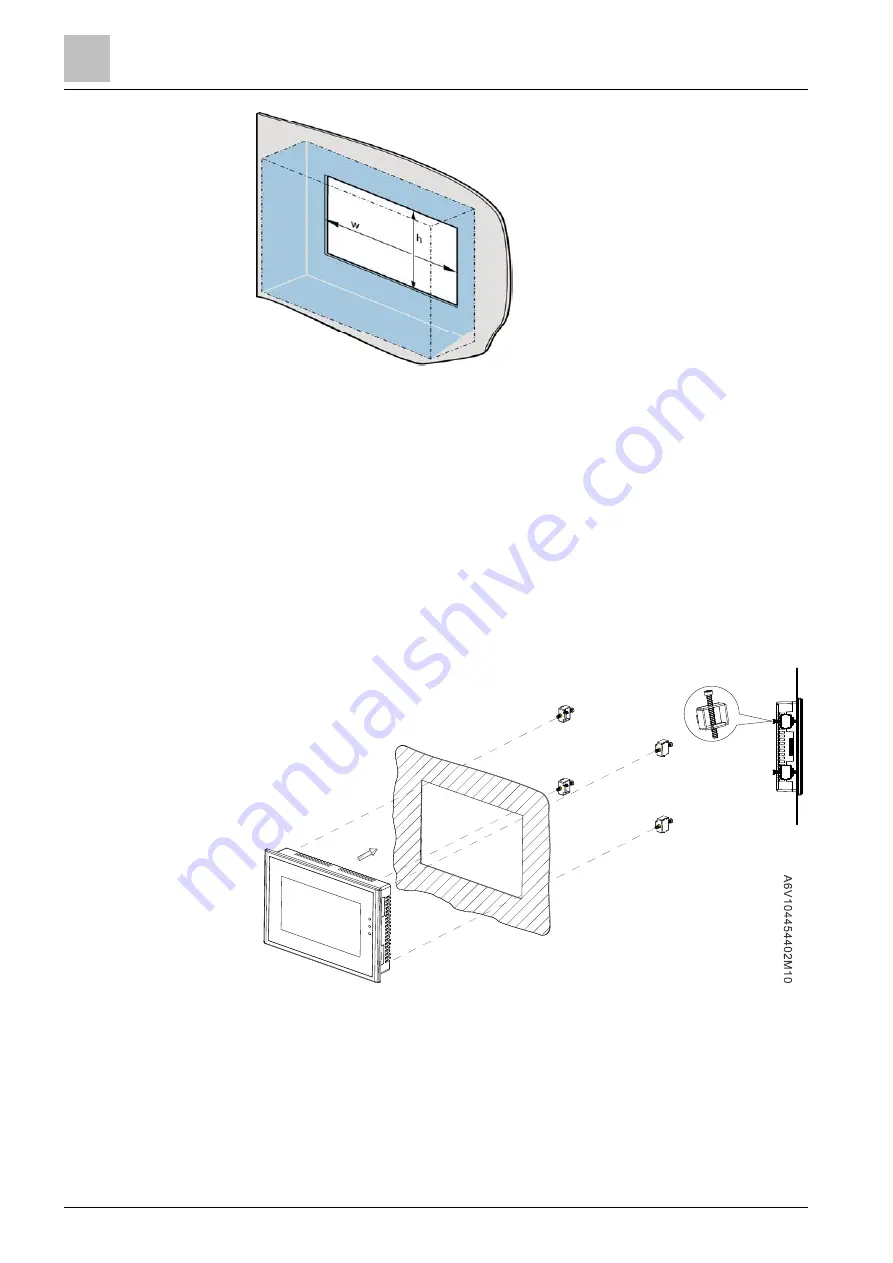
w  210 mm 

h  114 mm 


4.2


Mount the Climatix touch panel 


The material in the area of the mounting cutout must be sufficiently strong to 

ensure lasting and safe mounting of the Climatix touch panel. 


The force of the mounting clips or device operation may not cause the material 

to become deformed. 

1.


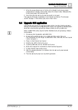
Insert the Climatix touch panel through the mounting cutout from the front. 

2.


Place the mounting clips into the corresponding cutout and hook them to the 

Climatix touch panel. 

3.


Tighten the mounting clips one by one to a torque of 0.2 Nm, until the Climatix 

touch panel is firmly mounted. (Type 7" touch panel uses four mounting clips.) 


To comply with the sealing specification, ensure that: 


Use all provided mounting clips. 


The maximum curvature of the mounting surface is 0.010". 

4.3


Connect the Climatix touch panel 

Workflow for connecting the Climatix touch panel: 

Note: 

Note: 

Summary of Contents for Climatix POL8T2.70/STD

Page 1: ...POL8T2 70 STD Climatix 7 inch capacitive touch panel Basic Documentation A6V11521026_en _b Smart Infrastructure 2020 10 15 ...

Page 2: ...ommunication 12 4 Mounting and connecting 13 4 1 Preparations 13 4 2 Mount the Climatix touch panel 14 4 3 Connect the Climatix touch panel 14 4 3 1 Connect power supply 15 4 3 2 Connect configuration PC 16 4 3 3 Connect Climatix controller 16 4 4 Switch on the Climatix touch panel 17 5 Operating the Climatix touch panel 19 5 1 Operate the touch screen 19 5 2 Operate the on screen keyboard 19 5 2 ...

Page 3: ...A6V11521026_en _b 3 31 8 Technical specifications 26 8 1 Technical data 26 8 2 Interface description 27 8 3 DIP switches 29 8 4 Dimensions 30 ...

Page 4: ......
Page 5: ...tal protection declaration A5W90006122 1 3 Accessories Description Product no ASN Min order quantity Touch panel communication cables for Climatix controller RJ45 connectors The cable length stretch is 2 0 m POL0C1 80 STD 10 Touch panel communication cables for Climatix controller RJ45 connectors The cable length stretch is 2 9 m POL0C1 75 STD 10 1 4 Before you start 1 4 1 Symbols and abbreviation...

Page 6: ...with the expressed permission of Siemens and may be provided only to authorized persons or companies with the requisite technical knowledge Siemens reserves the right to make any modification to this document without prior notice 1 4 4 Quality assurance This document was prepared with great care The content of all documents is checked at regular intervals Any corrections necessary are included in ...

Page 7: ...proper transport installation and commissioning as well as correct operation Fuses switches wiring and grounding must comply with local safety regulations for electrical installations The Climatix touch panel products may only be operated by personnel who have been instructed by Siemens Building Technologies or their delegates and whose attention has been drawn to potential risks When wiring the s...

Page 8: ...n over Modbus protocol Connection with multiple controllers Firmware upgrade using USB stick Graphical User Interface upgrade using PC and USB stick Programmable graphical interface with 3rd party multi language engineering tool Off line user interface simulation Multi language support Multi level passwords access Time scheduler and trend view functions via HMI TOOLS Data tag management via HMI TO...

Page 9: ...verview Topology 2 A6V11521026_en _b 9 31 Climatix POL6XX communication concept here C600 Climatix POL4XX communication concept here POL42X With Climatix POL6XX controller With Climatix POL4XX controller ...

Page 10: ...sign of the Climatix capacitive touch panel POL8T2 70 No Description No Description 1 Display touch screen 5 USB B port 2 Recesses for a mounting clip 6 USB A port 3 RS485 communication port and power supply 7 Label 4 Ethernet communication port and power supply 1 7 2 3 4 5 6 1 7 2 3 4 5 6 1 7 2 3 4 5 6 ...

Page 11: ...Overview Delivery scope 2 A6V11521026_en _b 11 31 2 4 Delivery scope Name Figure Quantity Touch panel 1 Mounting clips 4 Cable 1 ...

Page 12: ...t use in environment with sharp temperature change or in high humidity Otherwise the touch panel may be damaged due to internal condensation The Climatix touch screen is made of glasses Do not knock at it heavily or with pointed or sharp objects Otherwise you may damage the glasses and injure yourself 3 3 Notes on communication The touch panel supports the following connections to an external cont...

Page 13: ...ction classes The following clearances are required around the Climatix touch panel to ensure sufficient self ventilation x 10 mm y1 10 mm z 25 mm y2 75 mm Avoid mounting the Climatix touch panel near other devices AC power cable controller output module relay or other electrical equipment Keep the Climatix touch panel away from equipment such as frequency converters and power supply units and shi...

Page 14: ...med 1 Insert the Climatix touch panel through the mounting cutout from the front 2 Place the mounting clips into the corresponding cutout and hook them to the Climatix touch panel 3 Tighten the mounting clips one by one to a torque of 0 2 Nm until the Climatix touch panel is firmly mounted Type 7 touch panel uses four mounting clips To comply with the sealing specification ensure that Use all prov...

Page 15: ...rmitted rated voltage and the corresponding tolerance range Rated voltage Tolerance range DC 24 V 15 15 DC 20 4 27 6 V Separate the isolated DC power supply of the Climatix touch panel from a main AC power supply To comply with the ISC safety specification the maximum length of the DC power supply cable is 50 m shield cable or 30 m twisted pair cable Do not share the power supply of the Climatix t...

Page 16: ...can Transfer a project Reset the Climatix touch panel to factory settings Back up recover or configure recipes Use a USB cable to connect the configuration PC The USB cable has a standard USB Type B male connector on one end 1 Connect the USB cable to the USB A port on the Climatix touch panel 2 Connect the other end of the USB cable to the configuration PC 4 3 3 Connect Climatix controller If it ...

Page 17: ...o the service port of the controller For safety instructions see Notes on communication 12 Use the Ethernet port to connect to a Climatix controller 1 Shut down the Climatix touch panel 2 Connect an RJ45 connector side B without power branch on the communication cable in the product package to the LAN port of the Climatix touch panel 3 Connect the other RJ45 connector side A with power branch on t...

Page 18: ...ing up immediately switch off the power supply You have probably crossed the cables on the power supply terminal Check the connected cables and change them as needed Climatix touch panel has a DEMO application in order to show main functionalities and features Please download your own application developed with HMI TOOL configuration software ...

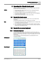
Page 19: ...screen of the Climatix touch panel You activate operating elements by touching them with your finger The Climatix touch panel provides a visual feedback as soon as it detects that an operating element has been touched The visual feedback is independent of any communication with the controller The visual feedback signal therefore does not necessarily indicate whether the relevant action was actuall...

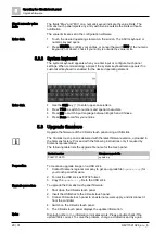
Page 20: ...ade firmware Upgrade the firmware of the Climatix touch panel using a USB stick The Climatix touch panel is delivered with the latest firmware version uploaded in the Siemens factory Proceed with the following instructions only if required by Siemens representative The following table lists the upgrade file name for the touch panel Product number Firmware upgrade file POL8T2 70 STD update zip To c...

Page 21: ...e configuration PC Users can upgrade it to the latest GUI application created with engineering software directly by using a USB stick Refer to HMI TOOL online help for further information about engineering software functionalities 1 Create your GUI application with HMI TOOL 2 Download the GUI application into a USB stick files as hmi hmz and hmi_model dat Do not change the default file name otherw...

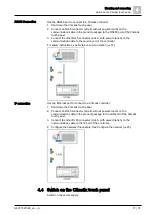
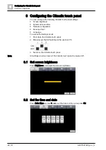
Page 22: ...onfiguration Serial port test Language To access the Settings mode 1 Shut down the Climatix touch panel 2 Manually set the DIP switches to the position 010 3 Switch on the Climatix touch panel All settings are stored even if the Climatix touch panel is powered off 6 1 Set screen brightness Press Brightness and adjust the screen brightness 6 2 Set the time and date Press Date time and use or to set...

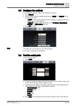
Page 23: ...s Subnet Mask Gateway and DNS address text box 3 Press Ok to confirm The button is not functional in the current release Port is only for application downloading 6 4 Test the serial ports To test the serial ports 1 Press Serial 2 Connect the desired serial port for example COM on the Climatix touch panel to a PC with serial port monitor software running 3 Configure the parameters in both HMI setti...

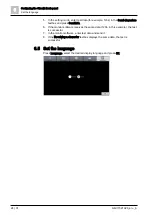
Page 24: ...racters textbox and press Senddata 6 If the monitor software receives the same data 1234 in this example the test is successful 7 In the monitor software enter test data and send it 8 If the Receiving a character textbox displays the same data the test is successful 6 5 Set the language Press Language select the desired display language and press Ok ...

Page 25: ...n edge inwards Use a cleaning cloth dampened with a cleaning agent to clean the equipment Only use water with a little liquid soap or a screen cleaning sponge When cleaning the touch screen you may inadvertently trigger a response on the controller by touching keys To prevent this switch off the Climatix touch panel prior to cleaning The Climatix touch panel may be damaged if compressed air steam ...

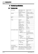
Page 26: ...ontrol No Brightness control Yes Contrast TYP 300 1 Brightness TYP 250 cd m2 Active display area 7 16 9 Environmental conditions Operation Temperature Humidity Atmospheric pressure 10 50 C 10 90 r h Min 700 hPa equal to max 3000 m above sea level Transport Temperature Humidity Atmospheric pressure 25 70 C 10 90 r h Min 260 hPa equal to max 10 000 m above sea level Protection Degree of protection F...

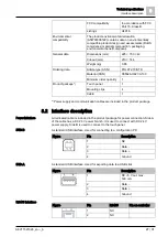
Page 27: ...mum order quantity 1 Product package Touch panel 1 Mounting clips 4 Cable 1 Power supply and communication cables are included in the product package 8 2 Interface description A dedicated cable is included in the product package for power connection Side A of the cable has a DC 24 V power branch It is used to connect with DC 24 V power supply Side B is used to connect to the touch panel A standard...

Page 28: ...ction 4 0 V 5 0 V 6 RS485 B RS485 B for RS485 connection 7 24 V 8 24 V Figure Pin LAN Pin on controller 1 TX TX 2 TX TX 3 RX RX 4 0 V 5 0 V 6 RX RX 7 24 V 8 24 V RS485 and LAN ports can also supply power If one port is powered with DC 24 V the other port will not be output as DC 24 V if no external power supply is connected IP interface Note ...

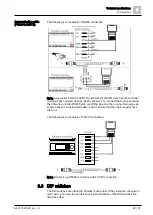
Page 29: ...ler RS485 port cut off the plug and then connect two wires as shown above If a customized cable is used ensure that the cable length is less than 3 m The following is an example of TCP IP connection Note Don t mix up RS485 connection with TCP IP connection 8 3 DIP switches The DIP switches are inside the Climatix touch panel If they would be changed in rare cases you need to open the housing Descr...

Page 30: ...mensions 8 30 31 A6V11521026_en _b DIP switches 1 3 Function 000 Normal operation mode 010 Setting mode 100 Calibrate the touch screen 101 Enter Android system 001 Firmware upgrade mode DIP switch status ON 1 OFF 0 8 4 Dimensions ...

Page 31: ...td Smart Infrastructure No 1 Fengzhi East Road Xibeiwang Haidian District 100094 BEIJING China 86 10 64768806 www siemens com buildingtechnologies Beijing Siemens Cerberus Electronics Ltd 2018 Technical specifications and availability subject to change without notice ...

Reviews: