51 / 244
Siemens
Standard application AHU
CE1P3977en_02
Building Technologies
Functions
01.02.2010
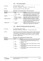
Parameter
Range
Function
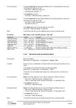
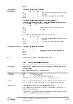
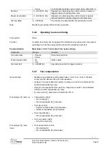
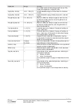
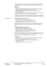
Fan steps type
Coding of digital outputs for fan control.
The number of outputs and possible Stepps (setpoints) depends on
the setting in TSP steps and also FanStep FreqConv, for analog
controlled variable speed drives.
Refer to explanation under General Operating Modes.
– Separated
– SepCombin
e
– Binary
– On digital output per stage and fan.
– Separate outputs on the first step, common outputs for addi-
tional steps.
– Outputs for the steps are binary coded. The setting is permitted
for Fan Type = direct or directVar.
Main Index > Unit > Fan Control
Functions not enabled in Configuration 1 and/or Configuration 2 are hidden.
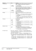
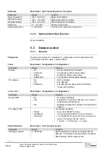
Parameter
Range
Function
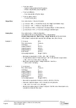
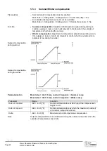
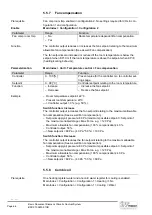
Supply fan
– Off
– Stage 1
– Stage 2
– Stage 3
Current supply air fan status. Go to parameter page for supply
air fan.
Exhaust fan
– Off
– Stage 1
– Stage 2
– Stage 3
Current exhaust air fan status. Go to parameter page for exhaust
air fan.
Actual step
– Off
– Stage 1
– Stage 2
– Stage 3
Current calculated, valid stage (setpoint for control) for fans.
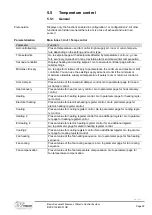
Fire mode
– Stop.
– RunSply
– RunExh
– Run both
Fan behavior in the event of a fire alarm:
– Fans are off.
– Only the supply air fan starts at the maximum enabled stage.
– Only the exhaust air fan starts at the maximum enabled stage.
– Both fans start at the maximum enabled stage.
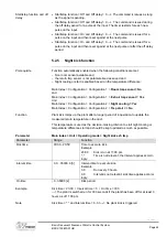
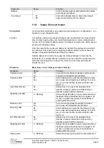
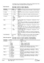
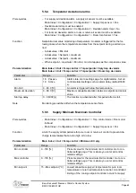
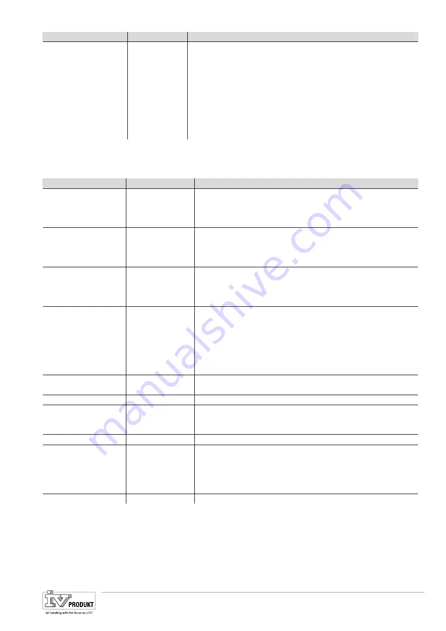
Fire setpoint
0…100 [%]
Output signal for fan start in the event of a fire alarm for all ana-
log controlled variable speed drives.
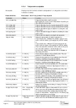
Slave offset
-999….999 [Pa]
Setpoint offset for fan control mode = Supply Slv or Exhaust Slv.
Slave start up stpt
0….999 [l/s]
Start setpoint for fan control mode = Exhaust Slv for exhaust fan
until the supply air fan is operating. The exhaust air fan then op-
erates using the Slave Offset setpoint.
Rundown time el htg
0…36000 [s]
Supply air fan overrun if an electrical heating register is active.
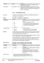
Min stage time
0…999 [s]
Minimum runtime for a stage prior to stepping up to the next
step.
Note: This period remains active when intervening using the op-
erator unit: Even for a direct jump from off to stage 3, the output
remains on each individual step for the minimum runtime.
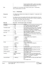
Coasting time
0..99 [s]
Coasting time when reducing each stage.
Parameterization
Basis Document Siemens Climatix Control System
BDCX.100820.01GB
Page 51

