Siemens Industry, Inc. 5300 Triangle Parkway, Norcross, GA 30092
A5E31166448A-006
Storage
Electrical control equipment which is to be stored prior
to its installation, should be checked before placing in
storage for possible damage during transit. It should
then be repacked and stored in a location which is
clean and dry.
When storage is in or near buildings under construc-
tion, provide covers to protect the equipment against
dust, moisture and falling objects.
Apparatus stored for long periods may cor
-
rode. Damage, while stored, will be minimized
by maintaining the best possible storage condi-
tions, and by periodically inspecting the equip-
ment and arresting the progress of corrosion and
other forms of deterioration which may be found.
A small amount of heat will stop corrosion that occurs
from moisture due to condensation.
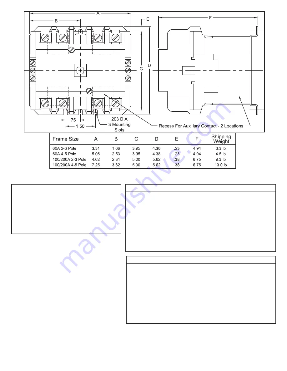
Fig. 6 Dimension Drawing 60, 100 and 200 Amp Device
CAUTION -
Coil must be wired correctly.
Risk of damage to the device.
All control wiring for contactor operation must only be made to
the coil isolation contact terminals #2, #3 and L2 terminal con-
nection points. Wiring made to any other terminal points will
burn out the coil and diode. If a coil burnout occurs, both the coil
and the diode must be replaced.
Table 6 - AC Operating Coils for 60 Ampere Contactors
Voltage
VAC
Freq.
Hz
Part Number
2-4 Pole 4-5 Pole
24
60 Hz
CLMD3C024
CLMD5C024
110/120
50/60 Hz
CLMD3C120
CLMD5C120
208
60 Hz
CLMD3C208
CLMD5C208
220/240
50/60 Hz
CLMD3C240
CLMD5C240
277
60 Hz
CLMD3C277
CLMD5C277
440/480
50/60 Hz
CLMD3C480
CLMD5C480
550/600
50/60 Hz
CLMD3C600
CLMD5C600
Table 7 - AC Operating Coils for 100 and 200 Ampere Contactors
Voltage
VAC
Freq.
Hz
Part Number
2-4 Pole 4-5 Pole
24
60 Hz
CLME3C024
CLME5C024
110/120
50/60 Hz
CLME3C120
CLME5C120
208
60 Hz
CLME3C208
CLME5C208
220/240
50/60 Hz
CLME3C240
CLME5C240
277
60 Hz
CLME3C277
CLME5C277
440/480
50/60 Hz
CLME3C480
CLME5C480
550/600
50/60 Hz
CLME3C600
CLME5C600


