© Siemens plc 2000 ¦
G85139-H1731-U450-B1
6
3
E-M BRAKE OPTION INSTALLATION (Continued)
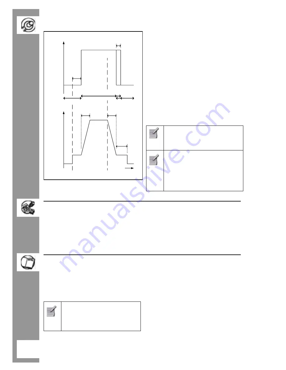
Fig. 2 External Brake Parameters
Brake Option Parameters:
P063
- External brake release delay.
When the inverter is set to RUN, it will
run at the minimum frequency for the
time set by the parameter, before
activating the E-M brake control relay
and releasing the brake (see Fig. 2).
Default value is 1.0s.
P064
- External brake stopping time.
This defines the period for which the
inverter continues to run at the minimum
frequency after ramping down and while
the E-M brake is applied.
Default value is 1.0s.
P063 and P064 settings should
be slightly longer than the actual
time taken for the E-M brake to
apply and release respectively.
P063 & P064 settings should be
kept as short as possible,
especially with a high minimum
frequency, as an overcurrent
warning or trip may result when
the inverter attempts to move a
locked motor shaft.
4
E-M BRAKE OPTION COMMISSIONING
The E-M brake option RL500 relay
operates the E-M brake, controlled by the
inverter software. The OPM2 Clear Text
Display option is required for inverter set-
up.
Apply mains power to the inverter and
access parameter P062 using the OPM2.
Using Fig. 2 as a guide, set P062 to P064
to enable and set-up the E-M brake
(disabled by default).
5
R BRAKE OPTION
The Case Size B COMBIMASTER and
MMI Resistor (R) Brake Option 6SE9996-
0XA11, integrates the E-M brake control,
together with a pulsed resistor braking unit.
Although 6SE9996-0XA11
incorporates E-M brake and R
brake options, the unit should
not be used as both E-M and
R brake simultaneously.
The R Brake option is not available for
Case Size A inverters.
The R Brake Option fits in place of the
existing inverter cover. Full IP65 protection
is maintained.
The E-M brake control is identical to that
previously described.
The pulsed R Brake Option gives the
COMBIMASTER and MMI increased
immunity to over-voltage trips. It can also
be used to provide up to 7kW (peak) of
braking power for stopping the system
more quickly than would otherwise be
possible.
~10ms
E-M Brake Option Output
[DC Average volts]
Inverter Frequency
[Hz.]
Time
[s]
RUN
Command
STOP
Command
0
Minimum
Frequency
Set Point
P002
P003
P064
P063
0
45% Vmains
OR
90% Vmains
Note: Idealised Waveform
FAST
SLOW
BRAKE ON
BRAKE ON
BRAKE OFF


