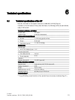
Technical specifications
6.2 Pinout of the Ethernet interface
CP 1543-1
80
Operating Instructions, 12/2019, C79000-G8976-C289-08
6.2
Pinout of the Ethernet interface
Pinout of the gigabit Ethernet interfaces
The table below shows the pin assignment of the Ethernet interface X1.
View of the RJ-45 jack
Pin
Signal name
Assignment
1
D1+
D1+ bidirectional
2
D1-
D1- bidirectional
3
D2+
D2+ bidirectional
4
D3+
D3+ bidirectional
5
D3-
D3- bidirectional
6
D2-
D2- bidirectional
7
D4+
D4+ bidirectional
8
D4-
D4- bidirectional
6.3
Permitted cable lengths - Ethernet
Permitted cable lengths - Ethernet
Alternative combinations per length range
0 ... 55 m
•
Max. 55 m IE TP Torsion Cable with IE FC RJ45 Plug 180
•
Max. 45 m IE TP Torsion Cable with IE FC RJ45 + 10 m TP Cord via
IE FC RJ45 Outlet
0 ... 85 m
•
Max. 85 m IE FC TP Marine/Trailing/Flexible/FRNC/Festoon/Food Cable with
IE FC RJ45 Plug 180
•
Max. 75 m IE FC TP Marine/Trailing/Flexible/FRNC/Festoon/Food Cable +
10 m TP Cord via IE FC RJ45 Outlet
0 ... 100 m
•
Max. 100 m IE FC TP Standard Cable with IE FC RJ45 Plug 180
•
Max. 90 m IE FC TP Standard Cable + 10 m TP Cord via IE FC RJ45 Outlet
See also Siemens Mall: (
https://mall.industry.siemens.com
6.4
Permitted cable lengths - Gigabit Ethernet
Permitted cable lengths - Gigabit
Ethernet
Alternative combinations
0 ... 60 m
•
Max. 60 m IE FC TP Flexible Cable GP 4x2 + 10 m TP Cord RJ45/RJ45 4x2
via IE FC RJ45 Modular Outlet Insert 1GE
0 ... 100 m
•
Max. 90 m IE FC TP Standard Cable GP 4x2 + 10 m TP Cord RJ45/RJ45 4x2
via IE FC RJ45 Modular Outlet Insert 1GE
See also Siemens Mall: (


