03/03
Installation and Commissioning
CP 243-1 IT
J31069-D0429-U001-A0-7618
49
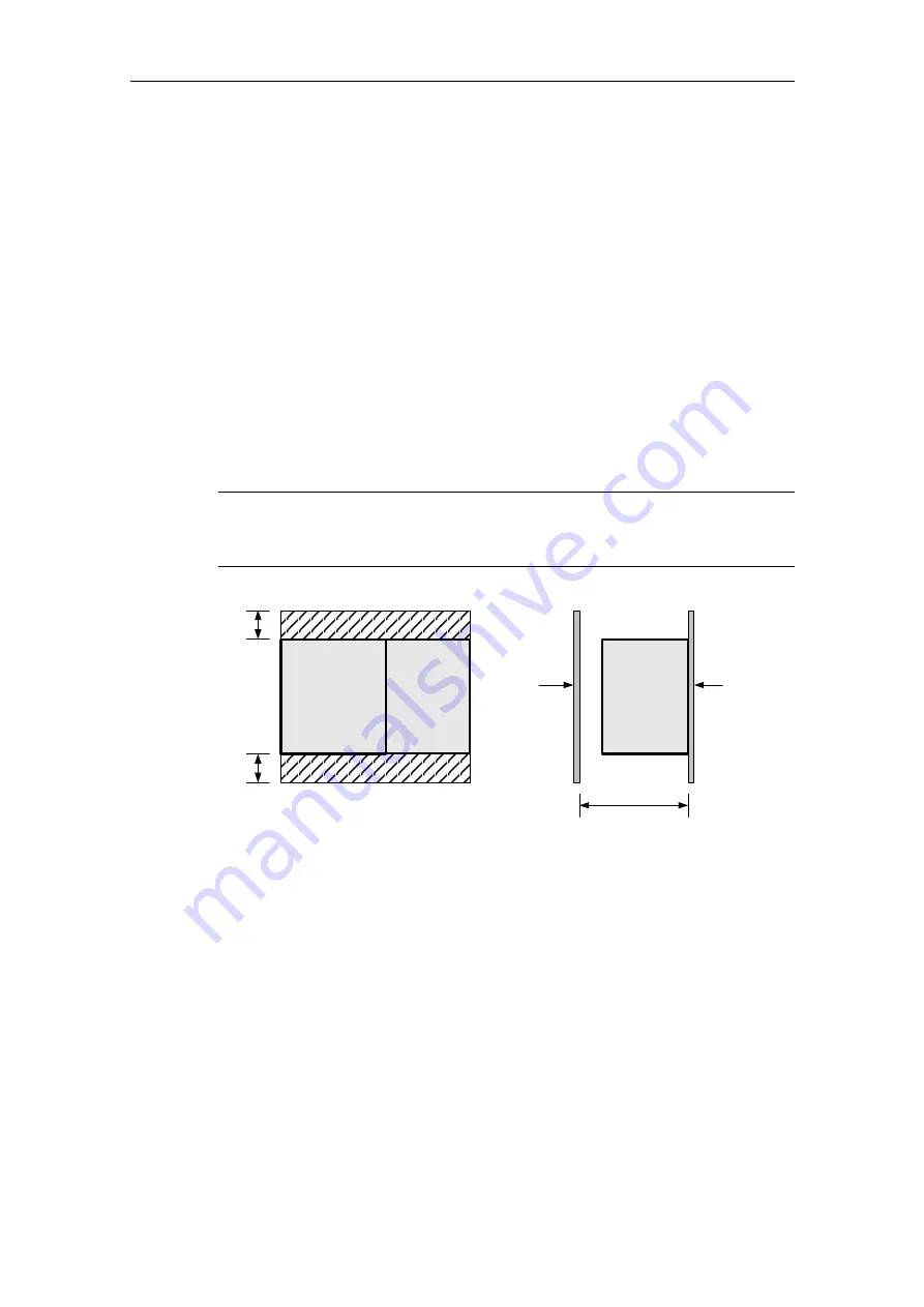
Space requirements during installation
When installing your module, adhere to the following guidelines.
•
The CP 243-1 IT is designed for natural heat dissipation by convection. For this
reason, leave at least 25 mm of free space above and below the device so that
the heat is free to escape. Long operating times at maximum ambient tempera-
tures and maximum loads will shorten the lifespan of the electrical components
of the device.
•
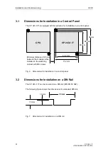
When installed horizontally, the CP 243-1 IT must always be installed to the
right next to the CPU.
•
When installed vertically, the maximum permissible ambient temperature drops
by 10 °C. The CP 243-1 IT must be positioned above the CPU. If you are using
a vertical standard DIN rail, you should use standard DIN rail stoppers to pre-
vent the module from slipping.
•
Installation depth is 75 mm.
Note
Set up your devices so that there is still enough space to wire the inputs and out-
puts and for the connections of the communication cables.
75 mm
CP 243-1 IT
Front
covering
Installation
space
View of side
CP 243-1 IT
25 mm
25 mm
View of front
S7-200
Distance to correct
heat dissipation
Fig. 5 Space requirements during installation
Summary of Contents for CP 243-1 IT
Page 46: ...Installation and Commissioning 03 03 CP 243 1 IT J31069 D0429 U001 A0 7618 46 ...
Page 94: ...Programming 03 03 CP 243 1 IT J31069 D0429 U001 A0 7618 94 ...
Page 106: ...Diagnosis 03 03 CP 243 1 IT J31069 D0429 U001 A0 7618 106 ...
Page 120: ...Technical Data 03 03 CP 243 1 IT J31069 D0429 U001 A0 7618 120 ...
Page 130: ...Example 03 03 CP 243 1 IT J31069 D0429 U001 A0 7618 130 ...

