background image

Specifications
Dimensions

8

44 | 56
Building Technologies

A6V10320094_m_en_--

Fire Safety

2017-10-31

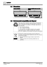
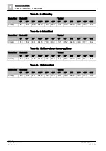
8.4 Dimensions

Interbase DBS72x

Interbase DBS72x with cover plate

BP720

8.5 Environmental compatibility and disposal

This equipment is manufactured using materials and procedures

which comply with current environmental protection standards as

best as possible. More specifically, the following measures have

been undertaken:

Use of reusable materials
Use of halogen-free plastics
Electronic parts and synthetic materials can be separated

Larger plastic parts are labeled according to ISO 11469 and

ISO 1043. The plastics can be separated and recycled on this basis.

The device is considered an electronic device for disposal in

accordance with the European Guidelines and may not be disposed

of as domestic garbage.

Dispose of the device through channels provided for this

purpose.
Comply with all local and currently applicable laws and

regulations.

5

1

.6

127.4

5

9

.3

127.4

Summary of Contents for DBS721

Page 1: ...DBS728 DBS729 Sounder interbase sounder beacon interbase sounder interbase with supplementary optical indication Technical Manual A6V10320094_m_en_ Building Technologies 2017 10 31 Control Products and Systems ...

Page 2: ...communication thereof to others without express authorization are prohibited Offenders will be held liable for payment of damages All rights created by patent grant or registration of a utility model or design patent are reserved Issued by Siemens Switzerland Ltd Building Technologies Division International Headquarters Theilerstrasse 1a CH 6300 Zug Tel 41 58 724 2424 www siemens com buildingtechn...

Page 3: ...g 17 3 5 Product version ES 17 3 6 Function 18 3 6 1 Configuration 18 3 6 2 Alarm levels and sound levels 18 3 6 3 Behavior in degraded mode 20 3 6 4 Service indicator 20 3 7 Accessories 21 3 7 1 Detector base with loop contact DB721 21 3 7 2 Cover plate BP720 21 3 7 3 Interbase seal RS721 22 3 7 4 Designation plate DBZ1193A 22 3 7 5 Detector locking device LP720 22 3 7 6 Micro terminal DBZ1190 AA...

Page 4: ...ications 38 8 1 Technical data DBS721 38 8 2 Technical data DBS728 40 8 3 Technical data DBS729 42 8 4 Dimensions 44 8 5 Environmental compatibility and disposal 44 9 Annex technical data 45 9 1 Tones and sound levels of the interbase 45 9 1 1 DBS721 and DBS729 tones 46 9 1 2 DBS728 tones 48 9 2 Optical beam characteristics of interbase DBS728 DC 32 V 51 9 3 Optical beam characteristics of interba...

Page 5: ...unction and for the products Has attended the training courses for Product Managers Project Manager Coordinates the deployment of all persons and resources involved in the project according to schedule Provides the information required to run the project Has obtained suitable specialist training for the function and for the products Has attended the training courses for Project Managers Installati...

Page 6: ... of international standard ISO 8601 format YYYY MM DD Conventions for text marking Markups Special markups are shown in this document as follows Requirement for a behavior instruction 1 2 Behavior instruction with at least two operation sequences Version option or detailed information for a behavior instruction Intermediate result of a behavior instruction End result of a behavior instruction Numb...

Page 7: ...se Sounder beacon interbase DBS721 DBS728 DBS729 A6V10320096 Installation Sounder interbase DBS721 Sounder interbase with supplementary optical indication DBS729 A6V10882301 List of compatibility for FC360 product line Please also observe the documentation for your fire detection system 1 2 Download center You can download various types of documents such as data sheets installation instructions an...

Page 8: ...uct line FC360 taken into account i 2015 11 16 Reference to EN 54 23 for the DBS728 removed from the Mounting site chapter Reference to EN 54 23 for cover plate added Amendments in the following chapters Structure and function Detector base seal RS720 Mounting Installation Annex technical data Seal label for cover plate added detector locking device LP720 for cover plate removed Editorial changes ...

Page 9: ...risks of injury Follow all measures identified by this symbol to avoid injury or death Additional danger symbols These symbols indicate general dangers the type of danger or possible consequences measures and prohibitions examples of which are shown in the following table General danger Explosive atmosphere Voltage electric shock Laser light Battery Heat Signal word The signal word classifies the ...

Page 10: ...ry is shown as follows WARNING Nature and origin of the danger Consequences if the danger occurs Measures prohibitions for danger avoidance How possible damage to property is presented Information about possible damage to property is shown as follows NOTICE Nature and origin of the danger Consequences if the danger occurs Measures prohibitions for danger avoidance ...

Page 11: ...idance and supervision of a qualified electrician in accordance with the electrotechnical regulations Wherever possible disconnect products from the power supply when carrying out commissioning maintenance or repair work on them Lock volt free areas to prevent them being switched back on again by mistake Label the connection terminals with external voltage using a DANGER External voltage sign Rout...

Page 12: ...al for activation this is generally the potential of the building installation Only check controls up to the interface relay with blocking option Make sure that only the controls to be tested are activated Inform people before testing the alarm devices and allow for possible panic responses Inform people about any noise or mist which may be produced Before testing the remote transmission inform th...

Page 13: ...tandards and directives complied with A list of the standards and directives complied with is available from your Siemens contact 2 5 Release Notes Limitations to the configuration or use of devices in a fire detection installation with a particular firmware version are possible WARNING Limited or non existent fire detection Personal injury and damage to property in the event of a fire Read the Re...

Page 14: ...base Two alarm levels can be activated for different events e g alarm and evacuation If a point detector is not used the blanking plate BP720 accessory can be fitted on the interbase Features Addressable on the C NET detector loop Communication with the control panel via the detector loop Supply via detector loop Compatible with all addressable detector bases from the Cerberus PRO product line Com...

Page 15: ...mmable brightness levels dark low and light high If a point detector is not used the blanking plate BP720 accessory can be fitted on the interbase Features Addressable on the C NET detector line Communication with the control panel via the detector loop Supply via detector loop Compatible with all addressable detector bases from the Cerberus PRO product line Compatible with all addressable point d...

Page 16: ...EN 54 23 11 tones are programmed in the interbase Two alarm levels can be activated for different events e g alarm and evacuation There are three programmable luminous intensity levels and two programmable flashing patterns This means that there are six adjustment options available If a point detector is not used the blanking plate BP720 accessory can be fitted on the interbase Features Addressabl...

Page 17: ...r device s product version On the packaging label On the product label or the type plate Product version on the packaging label Details of the product version can be found directly on the packaging label in the barcode Figure 4 Example of a packaging label with details of the product version Product version on the product label and the type plate Details of the product version can be found after t...

Page 18: ...stic and optical configuration 25 3 6 2 Alarm levels and sound levels Sounder interbase DBS721 The sounder interbase DBS721 can be activated for the following selectable alarm levels Warning Alert Evacuation EVAC The tone can be configured individually for each of the two selectable alarm levels from 11 different tones and the sound level can be configured by interbase There are three sound levels...

Page 19: ...or the following selectable alarm levels Warning Alert Evacuation EVAC The tone can be configured individually for each of the two selectable alarm levels from 11 different tones and the sound level can be configured by device There are three sound levels available One alarm sound level according to EN 54 3 and two test sound levels The LEDs have a set flashing frequency of about 0 8 Hz and can be...

Page 20: ...ed mode operation The interbases DBS721 DBS728 and DBS729 are also activated and deactivated in case of a fire alarm in degraded mode operation Degraded mode operation on the C NET is not supported in the same way by all control panels The information in the List of compatibility and in the corresponding control panel documentation must be taken into account during project planning 3 6 4 Service i...

Page 21: ...onnection via screw terminals Compatible with Multi sensor fire detector OH720 Smoke detector OP720 Heat detector HI720 Heat detector HI722 Multi sensor smoke detector ASA OOH740 Neural fire detector OOHC740 Interbase DBS72x Air sampling smoke detection kit FDBZ290 Order number S54319 F11 A1 See also 2 Mounting Installation 31 3 7 2 Cover plate BP720 To protect the interbase from dirt EN 54 23 Sel...

Page 22: ...1193A To identify the location Compatible with Base attachment wet FDB295 BA721 Base attachment surface mounted humid DBZ1192 DBW1171 base Interbase DBS72x Order number BPZ 4864330001 See also 2 Mounting Installation 31 3 7 5 Detector locking device LP720 For protection against theft Compatible with Multi sensor fire detector OH720 Smoke detector OP720 Heat detector HI720 Heat detector HI722 Multi...

Page 23: ...etector heating units sounder base external alarm indicators etc For conductor cross sections of 0 28 0 5 mm2 4 pin Order number BPZ 4677080001 3 7 7 Connection terminal DBZ1190 AB Auxiliary terminal for connecting cables For T branches of additional cabling e g for cable shielding detector heating units sounder base external alarm indicators etc For conductor cross sections of 0 5 2 5 mm 3 poles ...

Page 24: ...tor line Control panel FC20xx FC72x SIGMASYS AlgoRex FC361 xx C NET X X X compatible not compatible You will find details in the List of compatibility See also 2 Applicable documents 7 4 2 Fields of application Typical areas of use for the interbases DBS721 DBS728 and DBS729 include Hotel rooms Restrooms Offices 4 3 Mounting site The DBS721 and DBS729 interbases can be mounted on the ceiling or th...

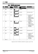
Page 25: ...zed Synchronizing optical signals between different device types DBS728 DBS729 DBS728 X DBS729 X X synchronization possible synchronization not possible 4 5 Acoustic and optical configuration The following chapters contain the specifications of the different acoustic signals and optical indicators The optical indicators are only available with interbases DBS728 and DBS729 See also 2 Configuration ...

Page 26: ...d SS 03 17 11 No 1 Imminent Danger 6 Intermittent 500 Hz 80 82 Swedish Standard SS 03 17 11 No 6 Local Warning 7 Continuous 500 Hz 82 83 Swedish Standard SS 03 17 11 No 4 All clear 8 Alternating 560 Hz 440 Hz 82 84 French fire sound NF S 32 001 1975 9 Intermittent 420 Hz 81 83 Australia Alert AS 2220 1978 10 Slow whoop Sweep up linear 500 Hz 1200 Hz 87 88 Australia Action AS 2220 1978 11 Intermitt...

Page 27: ...ernating2 0 8 Hz Normal 3 Flash 0 8 Hz Dark 4 Flash 0 8 Hz Bright 5 Flash 0 8 Hz Bright Monitoring function 1 6 Alternating2 0 8 Hz Bright 7 Reserve 1 Supervision function The LEDs are activated once approx every 4 5 hours and flash 4 times in succession 2 In alternating mode only half of the LEDs flash After a pause of 50 ms the other half flash See also 2 Optical beam characteristics of interbas...

Page 28: ...Part 3 EN 54 3 4 Slow whoop Sweep up linear 500 Hz 1200 Hz 88 90 NEN 2575 Netherlands EN 54 3 5 Pulse tone 500 Hz 86 89 Swedish Standard SS 03 17 11 No 1 Imminent Danger EN 54 3 6 Intermittent 500 Hz 86 89 Swedish Standard SS 03 17 11 No 6 Local Warning EN 54 3 7 Continuous 500 Hz 86 89 Swedish Standard SS 03 17 11 No 4 All clear EN 54 3 8 Alternating 560 Hz 440 Hz 86 88 French fire sound NF S 32 ...

Page 29: ... Standards at 12 V at 32 V 11 Intermittent 970 Hz 89 92 ISO 8201 US Temporal Tone LF EN 54 3 12 Sweep up 800 970 Hz 89 91 BS fire tone 13 Sweep up continuous slow whoop 150 1000 150 Hz 87 90 DE industrial alarm 31 Mute Alarm sounder is switched off so that the DBS728 can be operated as an optical indicator 1 The sound level depends on the angle See Annex technical data 0 5 s 1 5 s 0 0 5 s 970 Hz 1...

Page 30: ...ing Tool Listed as a duplicate of parameter 0 for backward compatibility 3 Flash 0 5 Hz Dark low Parameter is not visible in the Cerberus Engineering Tool Listed as a duplicate of parameter 0 for backward compatibility 4 Flash 0 5 Hz Light high 5 Flash 0 5 Hz Light high Monitoring function 1 6 Flash 0 5 Hz Light high Parameter is not visible in the Cerberus Engineering Tool Listed as a duplicate o...

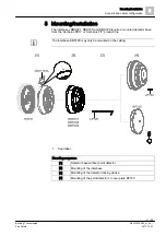
Page 31: ...bases DBS721 DBS728 and DBS729 require a mounted detector base from the Cerberus PRO or Cerberus FIT product line The interbase DBS728 may only be mounted on the ceiling 1 Seal label Mounting sequence 1 Detector base without point detector 2 Mounting of the interbase 3 Mounting of the detector locking device 4 Mounting of the point detector or cover plate BP720 ...

Page 32: ...reviously fitted point detector has been removed from the detector base 1 Install the required accessories LP720 DBZ1193A 2 Place the interbase on the detector base and turn it clockwise until it snaps into place 3 Place either the cover plate BP720 or the point detector on the interbase and turn it clockwise until it snaps into place a The interbase is connected to the detector base and ready for...

Page 33: ...inst theft Figure 8 Detector locking device LP720 1 Use the Allen key provided to insert the set screw into the interbase from the detector side by turning a few revolutions 2 Screw the interbase into the detector base 3 Screw the set screw back in until it touches the detector base The point detector mounted in the interbase can be protected against theft with another detector locking device LP72...

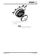
Page 34: ...urfaces to which the seal label 1 is to be attached are grease free 1 Place the cover plate BP720 on the interbase 2 Turn the cover plate clockwise until it snaps into place 3 Attach the self adhesive seal label 1 supplied see graphics The seal label 1 is attached above the sounder opening bar that is nearest to the horizontal zero point of the interbase Equal parts of the seal label 1 must be att...

Page 35: ...unting Installation Cover plate BP720 5 35 56 Building Technologies A6V10320094_m_en_ Fire Safety 2017 10 31 Figure 10 Position of the seal label 1 Seal label See also 2 Detector locking device LP720 22 1 ...

Page 36: ...ogies A6V10320094_m_en_ Fire Safety 2017 10 31 6 Commissioning The devices are commissioned via the control panel The exact procedure is described in the control panel documentation Conduct a performance check once commissioning is complete ...

Page 37: ...n_ Fire Safety 2017 10 31 7 Maintenance Repair 7 1 Status query The following actions can be performed from the control panel Commissioning Configure sounds Activate deactivate sound Activate deactivate LEDs only with interbases DBS728 and DBS729 Read error list status register ...

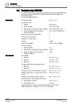
Page 38: ...minal DC 32 V Vnom Minimum DC 12 V Vmin Maximum DC 33 V Vmax Voltage at which the line separator opens Minimum DC 7 5 V VSO min Maximum DC 10 5 V VSO max Permanent current when switches are closed Max 1 5 A IC max Switching current e g in the event of a short circuit Max 2 A IS max Leakage current when switches are open Max 1 mA IL max Serial impedance when switches are closed Point detector not u...

Page 39: ...otection category IEC 60529 with interbase seal RS721 When using the point detector IP21C With blanking plate BP720 IP21C Electromagnetic compatibility at 1 MHz 1 GHz 50 V m 1 GHz 2 GHz 30 V m Mechanical data Dimensions Ø x H 127 4 x 51 6 mm Weight DBS721 225 g Weight BP720 27 g Material Polycarbonate PC Color Outside Translucent Body RAL 9010 pure white Standards European standards EN 54 3 type A...

Page 40: ...ctor 1 Separator connector factor 1 Protocol C NET System compatibility See List of compatibility Connection factor Sound activated 15 Light activated luminous intensity low high 13 32 Sound and light activated luminous intensity low high 23 43 Line separator Line voltage Nominal DC 32 V Vnom Minimum DC 12 V Vmin Maximum DC 33 V Vmax Voltage at which the line separator opens Minimum DC 7 5 V VSO m...

Page 41: ...vailable with all control panels 2 Luminous intensity according to EN 54 23 C 3 5 light high O 1 5 2 4 dark low ceiling mounted cylindrical cover cap as in Class C Ambient conditions Operating temperature 25 55 C Storage temperature 30 75 C Air humidity 95 rel Protection category IEC 60529 with interbase seal RS721 When using the point detector IP21C With blanking plate BP720 IP21C Electromagnetic...

Page 42: ... Separator connector factor 1 Protocol C NET System compatibility See List of compatibility Connection factor Sound activated 15 Light activated luminous intensity low medium high 6 16 26 Sound and light activated luminous intensity low medium high 21 31 41 Line separator Line voltage Nominal DC 32 V Vnom Minimum DC 12 V Vmin Maximum DC 33 V Vmax Voltage at which the line separator opens Minimum D...

Page 43: ...evels not available with all control panels 3 Adjustable maximum luminous intensity typical values at DC 32 V with blanking plate BP720 For details see Annex technical data 0 70 3 8 cd Ambient conditions Operating temperature 25 55 C Storage temperature 30 75 C Air humidity 95 rel Protection category IEC 60529 with interbase seal RS721 When using the point detector IP21C With blanking plate BP720 ...

Page 44: ...ollowing measures have been undertaken Use of reusable materials Use of halogen free plastics Electronic parts and synthetic materials can be separated Larger plastic parts are labeled according to ISO 11469 and ISO 1043 The plastics can be separated and recycled on this basis The device is considered an electronic device for disposal in accordance with the European Guidelines and may not be dispo...

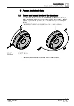
Page 45: ...cate the effective sound level of the DBS721 and DBS729 interbases a polar coordinate system is used in accordance with EN 54 3 Annex A The zero point 0 0 refers to the position of the alarm indicator AI in an inserted point detector The direction of rotation from horizontal to vertical is counter clockwise AI at 0 Horizontal AI at 90 Vertical The measurements were performed with cover plate BP720...

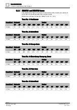
Page 46: ...Intermittent Sound level Horizontal Vertical 15 45 75 105 135 165 15 45 75 105 135 165 0 min 82 74 85 85 74 78 84 74 85 85 73 80 Tone No 3 Sweep down Sound level Horizontal Vertical 15 45 75 105 135 165 15 45 75 105 135 165 0 min 79 74 83 83 75 77 81 74 83 82 73 79 Tone No 4 Slow whoop Sweep up linear Sound level Horizontal Vertical 15 45 75 105 135 165 15 45 75 105 135 165 0 min 82 75 84 83 76 79...

Page 47: ...cal 15 45 75 105 135 165 15 45 75 105 135 165 0 min 78 71 79 80 72 75 78 70 80 80 69 77 Tone No 9 Intermittent Sound level Horizontal Vertical 15 45 75 105 135 165 15 45 75 105 135 165 0 min 75 70 79 79 70 73 75 71 80 78 68 74 Tone No 10 Slow whoop Sweep up linear Sound level Horizontal Vertical 15 45 75 105 135 165 15 45 75 105 135 165 0 min 81 75 84 83 78 75 82 75 85 83 76 80 Tone No 11 Intermit...

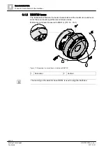
Page 48: ...8 tones The tables below illustrate the beam characteristics at the maximum sound level All of the sound levels specified are minimum values Minimum sound level measured in dBA 1 m DC 12 33 V Figure 11 Measuring the sound level on interbase DBS728 1 Horizontal 2 Vertical The marking on the detector base DB72x is used to align the interbase 1 2 ...

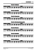
Page 49: ... 105 135 165 0 min 85 4 82 0 90 6 89 9 82 5 84 8 83 5 82 0 90 5 89 9 82 7 84 2 Tone No 4 Slow whoop Sweep up linear Sound level Horizontal Vertical 15 45 75 105 135 165 15 45 75 105 135 165 0 min 86 5 83 9 91 7 91 5 84 2 86 7 84 6 83 5 91 8 91 4 83 9 85 4 Tone No 5 Pulse tone Sound level Horizontal Vertical 15 45 75 105 135 165 15 45 75 105 135 165 0 min 81 6 76 0 86 3 85 9 76 6 81 9 79 2 75 3 86 ...

Page 50: ... No 9 Intermittent Sound level Horizontal Vertical 15 45 75 105 135 165 15 45 75 105 135 165 0 min 81 0 76 9 85 1 84 5 77 9 80 3 78 5 77 2 84 8 84 6 77 7 80 2 Tone No 10 Slow whoop Sweep up linear Sound level Horizontal Vertical 15 45 75 105 135 165 15 45 75 105 135 165 0 min 86 9 83 7 91 8 92 6 84 1 86 9 81 4 83 3 92 2 91 8 84 5 85 8 Tone No 11 Intermittent Sound level Horizontal Vertical 15 45 7...

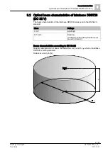
Page 51: ...rbase DBS728 DC 32 V The beam characteristics of the interbase DBS728 correspond to the EN 54 23 standard Class Settings C 3 5 Light high O 1 5 2 4 Dark low Ceiling mounted with cylindrical cover cap as in Class C Beam characteristics according to EN 54 23 Graphic representation of beam characteristics C x y and O x y when an interbase DBS728 is ceiling mounted Distances x and y in m x y ...

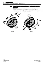
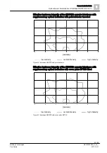
Page 52: ...al beam characteristics of interbase DBS729 DC 32 V To indicate the effective luminous intensity Ieff of the DBS729 interbase in accordance with the Blondel Rey law a polar coordinate system is used based on azimuth and elevation The zero point of the azimuth 0 relates to the position of the internal alarm indicator in the interbase DBS729 Azimuth Elevation ...

Page 53: ... optical indication with point detector inserted Figure 12 Interbase DBS729 with point detector Effective luminous intensity of the DBS729 sounder interbase with supplementary optical indication with cover plate BP720 fitted Figure 13 Interbase DBS729 with cover plate BP720 0 1 2 3 4 3 candela 2 1 0 1 2 3 high intensity normal intensity low intensity 0 1 2 3 4 3 candela 2 1 0 1 2 3 high intensity ...

Page 54: ... Elevation 52 Environmental compatibility 44 ES Product version 17 EU directives 38 40 42 F Fire control panel failure Degraded mode operation 20 I Interbase 9 L LEDs Flashing frequency 18 19 List of compatibility 7 20 24 Luminous intensity 15 16 43 52 O Order number 17 Original language 6 P Packaging label Product version 17 Polar coordinate system 52 Product label Product version 17 R Recycling ...

Page 55: ...Index 55 56 Building Technologies A6V10320094_m_en_ Fire Safety 2017 10 31 ...

Page 56: ...onal Headquarters Theilerstrasse 1a CH 6300 Zug 41 58 724 2424 www siemens com buildingtechnologies Siemens Switzerland Ltd 2011 Technical specifications and availability subject to change without notice Document ID A6V10320094_m_en_ Manual FD720 Edition 2017 10 31 Register 6 ...

Reviews: