background image

137/166 

Siemens 

RXB (KNX) application library 

FNC Description of functions for FC-10, FC-11, FC-12 CM110385en_05 

Building Technologies 

General and central functions 

28 Feb 2009 

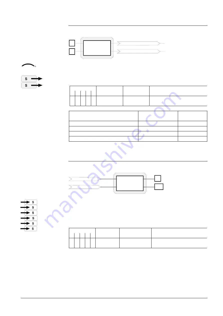
11.17.1  Digital inputs on the KNX bus 


D1

D2

RXB... Room controller

Digital input 1

Digital input 2

10385Z19en


The following S-mode input and output communication objects are used when taking 
advantage of spare inputs and outputs: 

Digital input 1 (Output communication object)


Digital input 2 (Output communication object)


Flags 
R W C T U 

Type Send 

heartbeat States 

1 0 1 1 0 

1.001   
DPT_Switch 

no 

0    (see 

11.2


Parameter setting in the tool 

Cause 
Digital input


Effect: 
Bus output 

Not used:  Bus = 1 = closed 

closed 


open 

Not used: Bus = 1 = open 

open 


closed 


11.17.2  KNX signals on digital/analog outputs 


Y1

Q24

RXB... Room controller

Triac Y1

Relay Q24

10385Z22en


Triac Y1  (Input communication object)


Triac Y2  (Input communication object)


Triac Y3  (Input communication object)


Triac Y4  (Input communication object)


Relay Q24 (Input communication object)


Relay Q34 (Input communication object)


Flags


R W C T  U 

Type Receive 

timeout 

States 

0 1 1 0 0 

1.001   
DPT_Switch 

no 

0 = Off  (voltage-free) 
1 = On   (AC 24V) 


KNX

R


CO


Summary of Contents for Desigo RXB

Page 1: ...ction guide RXC RXB RXL RXA 3 System overview DESIGO RXB 4 Hardware overview DESIGO RX 5 Data sheets RXB KNX Room controllers Room unit 6 CLC RAD Chilled ceiling and radiator applications 7 FNC Fancoil applications 8 RXB RXL Installation guide 9 CM110389en_06 30 Jun 2009 10 ...

Page 2: ......

Page 3: ...al Version 2 37 and higher s CM110389en_06 DESIGO RXB KNX Technical manual Version 2 37 and higher s CM110389en_06 DESIGO RXB KNX Technical manual Version 2 37 and higher s CM110389en_06 DESIGO RXB KNX Technical manual Version 2 37 and higher s CM110389en_06 DESIGO RXB KNX Technical manual Version 2 37 and higher s CM110389en_06 DESIGO RXB KNX Technical manual Version 2 37 and higher s ...

Page 4: ......

Page 5: ...ed ceiling and radiator systems CC 02 CM2N3874 QAX34 3 Room unit with PPS2 interface With temperature sensor setpoint adjustment Auto Fan speed switch with LCD display for room temperature and operating mode with HandyTool function CM2N1640 For more room units refer to the DESIGO RX hardware overview in Tab 04 Tab 06 CLC RAD Chilled ceiling and radiator applications Description of functions for CC...

Page 6: ......

Page 7: ...Building Automation Flexibility Functionality RXA RXB RXC Non communicating 10331Z01en RXL Proprietary Communications LONWORKS bus DESIGO RXC RXB RXL RXA Room automation systems Selection guide ...

Page 8: ...L and RXA are tailored to the various bus systems used in buildings RXC LON bus communication RXB KNX EIB bus communication RXL Proprietary communication RXA Stand alone non communicating RXC RXC offers the widest selection of HVAC applications and integrated applications incorporating lighting and blinds The RXC controllers are therefore suitable for more sophisticated HVAC applications where con...

Page 9: ...sing to integrated operation of HVAC lighting and blinds at room level Room unit functions QAX 30 1 31 1 QAX 32 1 QAX 33 1 QAX 34 1 QAX 34 3 QAX 84 1 PPS2 QAX 39 1 QAX 90 1 91 1 QAX 95 1 96 1 QAX 50 1 51 1 Built in room temperature sensor Room temperature setpoint adjustment QAX 31 1 QAX 91 1 QAX 96 1 Selection of operating mode Auto Selection of fan speed LCD display for room temperature operatin...

Page 10: ...tside air damper FNC20 Four pipe system with controlled air damper etc Variable air volume systems 01718 VAV01 Single duct supply or extract air system VAV02 Single duct supply air system with reheater or cooling coil VAV03 Single duct supply air system with electric re heater VAV04 Single duct supply and extract air system VAV05 Single duct supply extract air system with re heater cooler VAV06 Si...

Page 11: ...Building Automation RXB room automation system System overview ...

Page 12: ......

Page 13: ... room 5 Range overview 6 Coordinated room controllers 7 The room units the key to individual comfort 8 Applications 10 Installation 11 Engineering and commissioning 12 Integration into building automation and control systems 15 RXB overview 18 ...

Page 14: ...4 ...

Page 15: ... and create a sense of well being while at the same time saving energy One bus for HVAC lighting and blinds The RXB controllers perform all the HVAC functions while for the control of lighting and blinds various solutions are available on the market from different manufacturers This third party equipment is easy to combine with the RXB controllers due to the clarity of the KNX specifications the c...

Page 16: ...AX e g DELTA profil 10380z05en VAV Chilled ceilings Radiator type heating Lighting Blinds Fan coil units HVAC Electrical KNX components for electrical applications RXB24 1 RXB21 1 Controllers Operation RXB software Each RXB controller is loaded with software referred to in this document as the application comprising a set of HVAC applications The application actually required is enabled in the com...

Page 17: ...nd outputs The functions of the inputs and outputs are determined by the particular application and its parameters So for example the AC 24 V outputs can be configured either for thermic valve actuators or for 3 position actuators depending on the application Connections Functions RXB 21 1 22 1 24 1 Power supply AC 230 AC 230 AC 230 KNX bus PPS2 interface for standard room unit PPS2 Digital inputs...

Page 18: ...n The standard QAX room units are available for HVAC applications They are connected to the RXB controller via a special PPS2 interface In addition to the built in room temperature sensor the QAX3 und QAX9 room units incorporate a bus socket for the interface to the tool Wireless HVAC room operation The wireless room units types QAZ90 1 and QAX91 1 are used in conjunction with the RXZ90 1 receiver...

Page 19: ...de Auto 1 and fan speed LCD display for room temperature operating mode and fan speed PPS2 interface to RXB room controller Wireless room units 2 HandyTool Parameter setting for KNX RXB controllers 1 Operating mode Auto Comfort mode PreComfort Standby or Economy depending on control from the building automation and control system see page 15 2 For the QAX90 1 room units the PPS2 interface is the R...

Page 20: ...10 Two pipe system with change over outside air damper RXB21 1 FC 11 FNC12 4 pipe system with outside air damper RXB21 1 FC 11 FNC18 Two pipe system with change over and radiator RXB21 1 FC 11 FNC03 Two pipe system with change over and electric heater RXB22 1 FC 12 FNC05 Four pipe system with electric heater RXB22 1 FC 12 Common functions Window contact presence detector four operating modes Manua...

Page 21: ...on DIN rail In fan coil units In control panels In ceiling voids Under floors In sill or floor ducting 01654 Various options for installation Terminal covers are required when mounting the controllers outside control panels or fan coil units see page 18 Accessories 70227 Example RXB21 1 with terminal covers ...

Page 22: ...XB controllers Project structure Depending on the size of the building it may be advisable to create a project structure e g by dividing the building into floors or wings ETS3 supports this process with its own Building View A suitable bus structure can also be created with the ACS tool The HandyTool does not support this process Instead a separate addressing tool based on an Excel spreadsheet is ...

Page 23: ...setting For details please refer to documents CM110384 and CM110385 Communications links For the integration in building automation and control systems communications links are created by use of group addresses ETS3 ...

Page 24: ...ns for connecting the tools 1 10380z09en 3 Building autometion interface KNX 4 5 2 PPS2 PPS2 1 ETS3 or ACS connected to standard room unit 2 ETS3 or ACS connected to RXB controller 3 ETS3 or ACS connected to KNX bus 4 HandyTool connected to standard room unit 5 HandyTool connected to RXB controller via OCI700 USB KNX port ...

Page 25: ...omation system can be operated as a standalone system All the necessary functions can be implemented by means of the KNX communications between RXB controllers and between these and any KNX compatible third party equipment Integration into the automation level There are different possibilities for integrating RXB controllers into a building automation and control system The PX KNX integration stat...

Page 26: ...management station incorporates the following program modules for the user Graphics based operation of the site plant graphics Time schedules for a wide range of switching routines Display and modification of data point values Routing of alarm messages etc Example of a graphic user interface ...

Page 27: ... Auto 4 t Auto 17 00 22 00 Auto Room operating mode Comfort 1 Economy 3 Local Auto Central Room occupancy Central Building use Building use Room occupancy Example of the routines over a typical day 1 Comfort In this mode the room temperature is within the comfort range 2 PreComfort Standby The heating or cooling output is slightly reduced during the temporary absence of the room occupant 3 Economy...

Page 28: ...sh mounting room unit with temperature sensor setpoint adjuster Auto button fan speed and LCD indication CA2N1649 QAX90 1 Wireless room unit with temperature sensor CA2N1643 QAX91 1 Wireless room unit with temperature sensor and setpoint adjuster CA2N1643 RXZ90 1 Receiver with PPS2 interface for wireless room units CA2N1644 RXB commissioning aids RXT20 1 Service terminal CA2N3851 Integration inter...

Page 29: ...19 ...

Page 30: ...AG Building Technologies Group International Headquarters Gubelstrasse 22 CH 6301 Zug Tel 41 41 724 24 24 Fax 41 41 724 35 22 www siemens com sbt Building Automation Subject to technical change CM110380en_02 30 11 2007 ...

Page 31: ... GMA131 1E GQD121 1A GQD131 1A QAX30 1 QAX31 1 QAX39 1 BSGN U1 QAA24 QAA27 RXA20 1 RXA21 1 RXA22 1 RXB10 1 RXB21 1 RXB22 1 RXB24 1 NIEIBV2 Tool ETS3 Professional Tool ACS Service RXA29 1 QAA29 01 ALG QAA29 11 ALG Without PPS2 RXT20 1 QAX32 1 RXL21 1 RXL22 1 RXL24 1 OCI700 QAX34 3 HandyTool QAX33 1 RXT20 1 RXZ90 1 RXZ03 1 PXR QAX90 1 QAX91 1 Tool RXT10 3 RXZ01 1 RXZ02 1 QAX50 1 QAX51 1 PPS2 RXZ10 1...

Page 32: ...ors CA2N3834 X X X RXC30 1 Room controller for radiators and chilled ceilings with lighting control CA2N3840 X X RXC31 1 Room controller for VAV systems supply or extract air CA2N3844 X X X RXC32 1 Room controller for VAV systems supply air with built in pressure sensor CA2N3845 X RXC34 1 Room controller basic module for the control of fume hoods in laboratory rooms CA2N3847 X RXC34 1 ALG Controll...

Page 33: ...nd rocker switches for lighting and blinds RXC only communication LONWORKS CA2N1648 QAX60 1 QAX61 1 Old License for Intranet room operation 10 rooms with software DESIGO V1 only CA2B3807 QAX84 1 PPS2 QAZ84 1 RXZ80 1 PPS2 Flush mounted room unit with temp sensor setpoint adjustment Auto Fan speed switch and LCD display CA2N1649 QAX90 1 Wireless room unit with temperature sensor CA2N1643 QAX91 1 Wir...

Page 34: ...1N1962 X QPM2102 QPM2102D CO2 VOC sensor D with Display Replaces QPA63 1 AQP63 1 ARG64 CM1N1962 X QPM2160 QPM2160D CO2 T sensor D with Display new CM1N1962 X ARG64 replaced Duct mounting accessory set X QPA63 replaced CO2 VOC sensor CM1N1958 X AQP63 1 replaced Processor for ventilation demand for use with QPA63 CM1N1959 X Dew point sensor QXA2000 AQX2000 Condensation detector Supply unit CM1N1542 ...

Page 35: ...rmic actuator AC 24 V 105 N for radiator valves pluggable cable with optional LED display VD VE VU replaced by VDN VEN VUN VU Radiator valves CE1N2163 o o STP72 Push to open actuator CE1N4876 V P47 Small valves up to 4 m3 h CA1N4847 X X X V P47 S Small valves up to 4 m3 h Konnex CA1N4850 X X X STP72E Thermic actuator AC 24 V 105N for small valves pluggable cable with optional LED display 2W 4W 5W ...

Page 36: ... 5 mm 250 N M30 x 1 5 SSD Antrieb öffnet stossend CA1N4861 SSC Push to open actuator CA1N4895 SSC81 Motoric actuator AC 24 V 3P nominal stroke 5 5 mm self calibrating 300 N 3 4 V P45 over 6 3 m3 h CM1N4845 SSP51KNX Pull to open actuator CE1N4866 VDN VEN Radiator valves CE1N2105 CE1N2106 X o VUN Radiator valves CE1N2106 X o VPD VPE MiniCombi valves CE1N2185 X o VD CLC High flow rate CE1N2103 o X VD...

Page 37: ...1 1E 3 VAV static Compact air volume controllers consisting of static differential pressure sensor and configurable digital controller rotary actuator 5 10 Nm AC 24 V DC 0 10 V 3 position CM2N3544 X X X X Accessories RXZ01 1 LONWORKS bus terminator 52 3 Ω CA2N3861 RXZ02 1 LONWORKS bus terminator 105 Ω CA2N3861 RXZ03 1 discontinued LONWORKS point coupler for Version 1 plants only For Version 2 see ...

Page 38: ...CLC09 FNC02 FNC02 FNC03 FNC03 FNC03 FNC04 FNC04 FNC08 FNC10 FNC12 FNC18 FNC18 FNC20 FNC20 VAV01 VAV01 VAV02 VAV03 VAV04 VAV05 VAV06 VAV07 VAV08 VAV10 VAV14 FPB05 INT01 INT02 INT03 INT04 INT05 INT06 INT07 Actuator type coil STE71 STE72 STA71 STA72E STP71 STP72E 3rd party thermic SQS81 SSA81 SSB81 SSD81 x x x x x x x x x x x x x x x x x x x x x SSC81 SSP81 3rd party motoric Actuator type radiator ST...

Page 39: ...02 FNC04 FNC08 FNC20 VAV01 FNC02 FNC03 FNC04 FNC05 FNC08 FNC20 RAD01 CLC01 CLC02 FNC02 FNC03 FNC04 FNC05 FNC08 FNC10 FNC12 FNC18 FNC20 RAD01 CLC01 CLC02 FNC02 FNC03 FNC04 FNC05 FNC08 FNC10 FNC12 FNC18 FNC20 Actuator types Fancoil STE71 STE72 STA71 STA72E STP71 STP72E 3rd party thermic SQS81 SSA81 SSB81 SSD81 x x x x x x x x x x x x x x x x x x x x x x x x x x SSC81 SSP81 Motoric bus 3rd party moto...

Page 40: ...Old 2W 3W 4W Old Pull Push Equal Push Linear Push Pull For chilled ceil Push Push Actuators Thermic STA72E Pull 105 N X X STP72E Push 105 N X AL100 STA71 E Old X X STE71 1 Old X X STP71 E Old X AL100 STE72 Old X T W Motoric SSA81 Pull 100 N X NOT X SSB81 Push 200 N X X SSD81 Push 250 N X SSC81 Push 300 N X X SSP81 Push 160 N X AL100 SSP51KNX Push Pull 120 N X Set actuator to PULL X Set actuator to...

Page 41: ...ge over PI control Konnex bus communication S mode and LTE mode Integration into the DESIGO building automation and control system via PX KNX Integration into Synco Control of AC 24 V PDM 1 thermic valve actuators 3 position AC 24 V motorized valve and damper actuators or electric heating coils Use of motorized KNX EIB bus valves Volt free relay contacts for control of fans and electric heating co...

Page 42: ...m unit includes a tool function allowing you to parameterize the connected RXB controller Some of the applications do not make full use of all the inputs and outputs These I Os can be used freely in conjunction with a building automation and control system to register digital signals for example or to control various items of equipment ON OFF or pulse control with AC 24 V or volt free relay contac...

Page 43: ...ator FC 12 with RXB22 1 FNC03 2 pipe system with changeover and electric re heater FNC05 4 pipe system with electric re heater Only one application at a time can be activated with the tool ETS3 Professional Synco ACS or HandyTool Types The RXB21 1 and RXB22 1 room controllers differ only in the number of outputs available Type AC 24 V triac outputs Relay outputs RXB21 1 For 2 thermic valve actuato...

Page 44: ...ng base Service LED Programming pin Tool socket The programming LED shows the operational status of the room controller as follows Green flashing OK device is in operation Red ON Addressing mode ACS ETS Fault Orange green flashing Parameter download OFF No supply voltage Fault Service LED disabled by software Other patterns Start up approx 5 sec Fault The programming pin is used to identify the co...

Page 45: ...C Serial No Test date series Z A B C Observe notes in this document Activated application Location 3873Z04 010025CA9900 060215B 513 Options for use of the labeling fields Appl and Loc Handwritten identification of the location and the activated application group All terminals are detachable plug in screw terminals To avoid incorrect wiring terminals which can be connected to AC 230 V relay outputs...

Page 46: ... PPS2 RXB2 KNX PPS2 CP CP PPS2 Tool QAX3 RXZ90 1 PPS2 PPS2 3873A05 en KNX A A A CE CE CE CE KNX V24 ETS RS232 Siemens N148 UP146 UP152 A KNX USB ETS ACS Siemens OCI700 A C C B B Siemens Anschlusskabel Siemens Anschlusskabel HandyTool QAX34 3 HandyTool QAX34 3 The tool socket is a proprietary socket A Siemens connecting cable must be used e g PXA C1 When connected to Ethernet the device on the othe...

Page 47: ...ply cables connected to the room controller must be secured with cable restraints If serial wiring is applied on the terminal block 19 21 the connection will be inter rupted if the block is removed from the controller the jumpers 19 19 and 21 21 are on the PCB not in the block see terminal diagrams on pages 11 and 12 The supply cables must be secured with cable restraints The volt free relay outpu...

Page 48: ...e mounted in a cabinet or behind a cover that can only be opened removed with a key or a tool Ensure adequate air circulation to dissipate heat generated during operation Easy access is required for service personnel Local installation regulations must be observed Mounting instructions and a drilling template are printed on the controller packaging Commissioning The RXB2 room controllers are commi...

Page 49: ...rent DC 5 mA Contact transfer resistance Max 100 Contact insulation resistance Min 50 k Switch time min 20ms ON min 20ms OFF Measured value input B1 Compatible temperature sensors LG Ni 1000 Quantity 1 measuring range 0 50 C Sensor current 0 5 mA Resolution 0 1 K Measuring error at 25 C sensor temp without cable max 0 5 K Outputs AC24 V triac outputs Y1 Y4 Quantity 2 RXB22 1 4 RXB21 1 Output volta...

Page 50: ...cable Max 3 m Housing protection standard Protection standard to EN 60529 IP30 with terminal cover fitted and wall mounted without DIN rail IP20 for all other mounting arrangements Protection class Suitable for use in systems with protection class I or II Ambient conditions Normal operation Class 3K5 to IEC 60721 3 3 Temperature 0 50 C Humidity 85 rh Transport Class 2K3 to IEC 60721 3 2 Temperatur...

Page 51: ...t G 11 AC 24 V actuator supply Y4 12 AC 24 V 0 5 A switching output Room unit CP 13 PPS2 ground CP 14 PPS2 data CE 15 KNX EIB data cable CE 16 KNX EIB data cable KNX EIB bus plug in connection CE 17 KNX EIB data cable CE 18 KNX EIB data cable Power supply N 19 Neutral conductor R 21 Phase conductor AC 230 V 10 Relay outputs Q13 25 Common feed for Q14 Q24 and Q34 Q14 26 Normally open contact max AC...

Page 52: ...2 ground CP 14 PPS2 data CE 15 KNX EIB data cable CE 16 KNX EIB data cable KNX EIB bus plug in connection CE 17 KNX EIB data cable CE 18 KNX EIB data cable Power supply N 19 Neutral conductor R 21 Phase conductor AC 230 V 10 Relay outputs Q13 25 Common feed for Q14 Q24 and Q34 Q14 26 Normally open contact max AC 250 V 5 4 A Stage 1 Q24 27 Normally open contact max AC 250 V 5 4 A Stage 2 Q34 28 Nor...

Page 53: ...rmic valve actuators Y1 1 Motorized AC 24 V 3 position valve or damper actuator Y3 1 Motorized AC 24 V 3 position valve or damper actuator B2 QAX room unit Q1 3 speed fan Q1 1 1 speed fan Q2 Electric heating coil Twisted pair Fans connected to relay outputs Q14 Q34 must not be operated in parallel For parallel operation use cut off relays or slave room controllers At Q2 1 8 kW max resistive load u...

Page 54: ...al transformer and the power supply of the UA1T this could cause the valve positions to deviate substantially AC 230 V 3873Z12 Y1 N1 L N Y1 G L N Y1 1 1 2 3 4 NS LS COM X1 AC 24 V Y1 1 Y1 2 3873Z13 Y1 8 7 6 5 COM Y1 COM Y1 N2 1 2 3 4 NS LS COM X1 Y1 5 Y1 6 8 7 6 5 COM Y1 COM Y1 N2 G G0 Y1 3 Y1 4 Y1 7 Y1 8 N1 L N Y1 G AC 230 V L N N1 Room controller RXB21 1 RXB22 1 N2 UA1T power amplifier see data ...

Page 55: ...XB22 1 Room controllers CM2N3873en_06 Building Technologies 02 Apr 2010 Dimensions Without terminal cover 62 1 3 9 35 3 133 2 3873M14 3 3 4 4 With terminal covers 62 1 3 9 35 3 167 112 4 107 8 51 5 5 3873M15 Dimensions in mm ...

Page 56: ...16 16 Siemens RXB21 1 RXB22 1 Room controllers CM2N3873en_06 Building Technologies 02 Apr 2010 86 3 43 2 78 39 3873M16 3 6 Drilling diagram 1 1 2006 2010 Siemens Switzerland Ltd Subject to alteration ...

Page 57: ... chilled ceiling and radiator systems PI control Konnex bus communication S mode and LTE mode Integration into the DESIGO building automation and control system via PX KNX Integration into Synco Control of AC 24 V PDM 1 thermic valve actuators or 3 position AC 24 V motorized valve actuators Use of motorized KNX EIB bus valves Commissioning with ETS3 Professional Synco ACS or HandyTool AC 230 V ope...

Page 58: ... various items of equipment ON OFF or pulse control with AC 24 V The inputs can then be read and the outputs controlled via the building automation and control system Not suitable for time critical processes 1 s Functions The room controller functions are determined by the selected application and its parameters and by the input output configuration For details refer to the CLC and RAD description...

Page 59: ...bility The RXB24 1 room controller is compatible with field devices from Siemens Building Technologies and with KNX EIB compatible third party devices For details refer to the DESIGO RX hardware overview CA2N3804 Design The RXB24 1 controller consists of a housing base a housing cover and the printed circuit board with connection terminals The controller also has a tool socket a service LED and a ...

Page 60: ...til identification of the controller is complete Once the programming pin has been pressed the tool overwrites the hardware address in the room controller If there are no terminal covers fitted the programming pin may be operated only by a qualified electrician The adjacent terminal may be a live mains voltage conductor Terminal covers RXZ20 1 are available as an option to protect the connection t...

Page 61: ...an be connected to AC 230 V are physically separate from the other terminals Warning The cable restraints on the housing base must be used for the connections to terminals 19 21 AC 230 V The conductors must be secured with cable ties see diagram Ensure that the power is off before inserting or removing plug in terminals connected to a mains voltage 3873J04 The RXB24 1 controller communicates with ...

Page 62: ...y be damaged The tools ETS3 and ACS even if connected to a tool socket require an interface RS232 KNX EIB interface ETS3 OCI700 USB KNX EIB interface ETS3 ACS The HandyTool is connected to the tool socket of the room controller or to the tool socket of the room unit QAX3 RXZ90 1 B If you use OCI700 as an interface it is connected to the service plug of the controller or of the room unit As long as...

Page 63: ...wer supply cables depends on the total load and on local regulations The power supply cables connected to the room controller must be secured with cable restraints If serial wiring is applied on the terminal block 19 21 the connection will be inter rupted if the block is removed from the controller the jumpers 19 19 and 21 21 are on the PCB not in the block see terminal diagrams on pages 11 and 12...

Page 64: ...unting It must be mounted in a cabinet or behind a cover that can only be opened removed with a key or a tool Ensure adequate air circulation to dissipate heat generated during operation Easy access is required for service personnel Local installation regulations must be observed Mounting instructions and a drilling template are printed on the controller packaging Commissioning The RXB24 1 room co...

Page 65: ...I Inputs Signal inputs D1 D2 Quantity 2 for volt free contacts Contact voltage DC 16 V Contact current DC 5 mA Contact transfer resistance Max 100 Contact insulation resistance Min 50 k Switch time min 20ms ON min 20ms OFF Measured value input B1 Compatible temperature sensors LG Ni 1000 Quantity 1 measuring range 0 50 C Sensor current 0 5 mA Resolution 0 1 K Measuring error at 25 C sensor temp wi...

Page 66: ... or II Ambient conditions Normal operation Class 3K5 to IEC 60721 3 3 Temperature 0 50 C Humidity 85 rh Transport Class 2K3 to IEC 60721 3 2 Temperature 25 65 C Humidity 95 rh Standards and directives Product safety Automatic electronic controls for household and similar use EN 60730 1 Electromagnetic compatibility Immunity industrial domestic EN 60730 1 Emissions domestic EN 60730 1 Home and Buil...

Page 67: ... A switching output G 8 AC 24 V actuator supply Y2 9 AC 24 V 0 5 A switching output Y3 10 AC 24 V 0 5 A switching output G 11 AC 24 V actuator supply Y4 12 AC 24 V 0 5 A switching output Room unit CP 13 PPS2 ground CP 14 PPS2 data CE 15 KNX EIB data cable CE 16 KNX EIB data cable KNX EIB bus plug in connection CE 17 KNX EIB data cable CE 18 KNX EIB data cable Power supply N 19 Neutral conductor R ...

Page 68: ... B1 LG Ni 1000 temperature sensor D1 D2 Volt free contacts window contact occupancy sensor etc Y1 Y4 AC 24 V thermic valve actuators Y1 1 Motorized AC 24 V 3 position valve actuator Y2 1 Motorized AC 24 V 3 position valve actuator B2 QAX room unit Twisted pair For information on the compatibility of field devices with the RXB24 1 room controller refer to the various application descriptions see th...

Page 69: ...al transformer and the power supply of the UA1T this could cause the valve positions to deviate substantially AC 230 V 3873Z12 Y1 N1 L N Y1 G L N Y1 1 1 2 3 4 NS LS COM X1 AC 24 V Y1 1 Y1 2 3873Z13 Y1 8 7 6 5 COM Y1 COM Y1 N2 1 2 3 4 NS LS COM X1 Y1 5 Y1 6 8 7 6 5 COM Y1 COM Y1 N2 G G0 Y1 3 Y1 4 Y1 7 Y1 8 N1 L N Y1 G AC 230 V L N N1 Room controller RXB24 1 N2 UA1T power amplifier see data sheet CA...

Page 70: ...4 1 Room controller CM2N3874en_04 Building Technologies 02 Apr 2010 Dimensions Without terminal cover 62 1 3 9 35 3 133 2 3873M14 3 3 4 4 With terminal covers 62 1 3 9 35 3 167 112 4 107 8 51 5 5 3873M15 Dimensions in mm ...

Page 71: ...15 16 Siemens RXB24 1 Room controller CM2N3874en_04 Building Technologies 02 Apr 2010 86 3 43 2 78 39 3873M16 3 6 Drilling diagram 1 1 ...

Page 72: ...16 16 Siemens RXB24 1 Room controller CM2N3874en_04 Building Technologies 02 Apr 2010 2007 2010 Siemens Switzerland Ltd Subject to change ...

Page 73: ... individual room control system to measure the room temperature and for operation of a room controller The functions of the LCD display are determined by the controller If manual fan speed control is enabled the room unit can be used to operate a fan coil system It is also suitable for use in conjunction with a DESIGO PX automation station 1 In conjunction with the RXB RXL controllers FC 10 and la...

Page 74: ...an the actual state Mechanical design The room unit is suitable for mounting on a recessed conduit box The cable entry is through the rear For surface mounting with the cable entry at the top or bottom accessory ARG70 2 is required Basically the unit comprises the housing and the mounting plate These can be locked together and released by a snap mechanism The mounting plate incorporates the screw ...

Page 75: ...display switches from room temperature to setpoint display Each additional operation of the upper or lower button increases or reduces the setpoint by 0 5 K or 1 0 F the engineering unit is predeter mined by the controller The maximum possible adjustment range is also defined by the controller The following display options are possible in normal operation actual options determined by the controlle...

Page 76: ...e as currents of air in the conduit can affect the sensor reading The admissible ambient conditions must be observed Mounting instructions are enclosed with the device A set of fixing accessories is enclosed with the device Installation Local installation regulations must be observed The equipment is not protected against accidental connection to AC 230 V Commissioning After an interruption of the...

Page 77: ...re a room controller has sent a value S Room controller has not transmitted a valid temperature value S S Static error The error display remains valid until the error has been cleared D Dynamic error For 5 s after its occurrence the error is displayed instead of the room temperature The display then reverts to normal If the error persists it can be displayed again by pressing the or button Pressin...

Page 78: ... RXC CA110334 DESIGO RXB RXL CM110381 DESIGO RXA CA2Z3884 DESIGO PX CA110396 Cable type 2 core twisted pair unscreened Housing protection Protection standard to EN 60529 IP 30 Protection class Insulation protection class III Ambient conditions IEC 721 Normal operation Transport Environmental conditions Class 3K5 Class 2K3 Temperature 0 50 C 25 70 C Humidity 85 rh 95 rh Mechanical conditions Class ...

Page 79: ...04 CP CP PPS2 interface power supply CP 1 Device power supply PPS2 data positive CP 2 Device power supply PPS2 data negative The example below shows the room unit connected to a DESIGO RXB room controller 1640A05 PPS2 R1 2 1 CP CP N1 CP CP Twisted pair R1 QAX34 3 room unit N1 RXB room controller Terminal layout Wiring diagram ...

Page 80: ... Room unit with PPS2 interface CM2N1640en_04 Building Technologies 30 Jun 2009 Dimensions 89 45 4 28 28 28 28 26 30 35 30 11 8 112 3 96 119 23 8 1640M07 Dimensions in mm 2006 2009 Siemens Switzerland Ltd Subject to change ...

Page 81: ...r CC 02 CLC and RAD applications see document CM110671 Related documents CM1Y9775 RXB integration S mode CM1Y9776 RXB RXL integration Individual addressing CM1Y9777 Third party integration CM1Y9779 Working with ETS CM110384en_03 28 Feb 2009 Siemens Building Technologies ...

Page 82: ...xample 27 3 4 Heating and refrigeration demand zones 28 4 Applications Parameters 29 4 1 Select application 29 4 2 Parameter settings 30 5 Room operating modes 31 5 1 Description 31 5 2 Overview 32 5 3 Determine the room operating mode with DESIGO S mode 33 5 3 1 Local control of room operating mode via a window contact 34 5 3 2 Central control of room operating mode via input from the Use schedul...

Page 83: ...point shift 72 7 Temperature measurement 74 7 1 Room temperature measurement 74 7 1 1 Local temperature sensor at PPS2 interface 74 7 1 2 Local temperature sensor at analog input 74 7 1 3 Averaging analog input PPS2 interface 75 7 1 4 Sensor correction 75 7 1 5 Temperature sensor outputs on the Konnex bus 76 7 1 6 Temperature sensor input from Konnex bus 77 7 2 Outside air temperature via Konnex b...

Page 84: ...ng the sensor B1 to the Konnex bus 112 10 16 Software version 113 10 17 Device state 113 11 Room unit 114 12 KNX information 117 12 1 Reset and startup response 117 12 2 LED flashing pattern 117 12 3 Startup delay 118 12 4 Bus load 118 12 5 S mode communication objects for RAD CLC 119 12 5 1 S mode input communication objects 119 12 5 2 S mode output communication objects 120 12 6 LTE mode communi...

Page 85: ...owledge 1 3 Quality assurance These documents have been prepared with great care The contents of all documents are checked at regular intervals Any corrections necessary are included in subsequent versions Documents are automatically amended as a consequence of modifications and corrections to the products described Please ensure that you are aware of the latest revision date of the documentation ...

Page 86: ...sociated with the use of the documentation please do not hesitate to contact the Product Manager at your nearest branch office or write directly to the support team at our Swiss headquarters E mail fieldsupport zug ch sbt siemens com Please note that without prejudice to your statutory rights Siemens accepts no liability for any losses resulting from non observance or improper observance of the po...

Page 87: ...according to the number of controllers We recommend the following products Manufacturer Type Designation Siemens Building Technologies ACX95 320 ALG Power supply 320 mA Siemens Automation and Drives 5WG1 125 1AB01 Power supply 160 mA 5WG1 125 1AB11 Power supply 320 mA 5WG1 125 1AB21 Power supply 640 mA 1 7 RXB Konnex controller communications The RXB Konnex controllers support communications as de...

Page 88: ...put or output has a precisely defined name Whenever an output and an input with the same name are located in the same zone a connection is established automatically as shown in the following diagram Controller Valve Sensor Time switch zone 1 1 1 Outside temperature zone 3 Geogr zone 2 5 1 Geogr zone 2 5 1 Heat distr zone 1 Cooling coil Outside temperature 10385Z01en Outside temperature Cooling coi...

Page 89: ...t Graphical symbol for an LTE input communication object Graphical symbol for an S mode output communication object Graphical symbol for an LTE output communication object The communication objects of the RXB Konnex controllers work in part in S mode in part in LTE mode and in part in both modes These objects are described accordingly The following table describes each communication object working...

Page 90: ...cribed in the Konnex specification 4 The devices listed here manufacturer and type are suitable partners for the communication object For a list of all the LTE mode communication objects used refer to section 12 6 For details of the Konnex data types refer to Section 12 7 The left margin contains the symbol for the HandyTool next to a table containing the parameter number short name and default va...

Page 91: ...one s right When you use an OCI700 as the interface connect it to the controller s or room unit s service socket The OCI700 must be powered via USB by the computer as long as it is connected to the service socket Otherwise the LCD display for the room device goes dark and the controller goes to addressing mode 2 3 Parameterization with ETS3 Professional This manual does not describe how physical a...

Page 92: ...gies Definitions Tools 28 Feb 2009 2 4 Parameterization using ACS This manual does not describe how physical addresses are defined This information can be found in the ACS description In the ACS Service program select Plant Open to open the plant To start parameterization select Applications Parameter settings ACS Service ...

Page 93: ...sible in the room controllers Parameters Physical address Zones Group addresses bindings cannot be assigned This must be carried out in ETS In addition to its room unit functionality this device also allows for parameterizing room controllers If the room controller was preprogrammed via ETS3 ACS or HandyTool Physical address Zones when in LTE mode Setpoints Master slave settings All parameters The...

Page 94: ... 0 Use and or to choose between the following modes 0 Normal mode normal room unit functions 2 Display mode The parameters are displayed with prefix d e g d015 Press to find the number and confirm with Enter This displays the corresponding value Press Enter or Escape to return to the list 3 Parameterization mode Allows you to set selected parameters see below They are displayed with prefix P e g P...

Page 95: ...11 Time switch zone apartment if LTE is set P012 Time switch zone room if LTE is set P013 Time switch zone subzone if LTE is set P016 Heat distr zone heating surface if LTE is set P017 Refrig distr zone cooling surface if LTE is set P018 Outside temperature zone if LTE is set P021 Master Slave P023 Master Slave zone group if LTE is set P031 Economy cooling setpoint P032 Precomfort cooling setpoint...

Page 96: ...e see 2 5 2 3 Parameterization mode see 2 5 2 4 Upload see 2 6 5 Download see 2 6 6 Service mode All parameters can be set They are displayed with prefix S e g S053 Press to find the number and confirm with Enter This displays the corresponding value Press to change the value and confirm with Enter Press Escape to return to the selection without changing anything Press Escape again to return to th...

Page 97: ...ons and simultaneously for approx 2s Æ The display goes dark Press button twice briefly The display now shows 0 mode 0 Use and or to choose between the following modes 0 Normal mode normal room unit functions 1 Test mode see 2 7 2 Display mode see 2 5 2 3 Parameterization mode see 2 5 2 4 Upload 5 Download 6 Service mode If 4 or 5 is displayed this mode can be selected via Enter The storage number...

Page 98: ...ownload see 2 6 6 Service mode The following positions can be selected depending on the type of parameterization They are displayed with prefix T The list shows all theoretically possible positions However only positions that are available for selection based on the type of parameterization are displayed Theoretically possible positions for periphery testing T 01 Sensor input B1 9 Value of B1 in C...

Page 99: ...Operates only the I Os of the controller in test mode no bus actuators 9 Values are correct when read but will not automatically be updated The positions can be selected with Enter The inputs are displayed Outputs can be set via Enter and To exit test mode press Escape 2 3 times depending on the situation If no further button is pressed for 5 minutes the controller automatically reassumes Normal m...

Page 100: ...sed in S mode when networked with the DESIGO automation and control system and in LTE mode with Synco The factory setting of all controllers and the basic setting of the tools is 0 S Mode This minimizes the bus load Exception ACS Service changes the setting immediately to 1 LTE S The ETS3 Professional is used in DESIGO networks It can be used for operation in S mode LTE mode and S mode The send he...

Page 101: ...or example Apartment can be used to refer to a group of rooms floor or section of a building Room however really does refer to a room Subzone is unlikely to be used much for HVAC devices it is more relevant to other disciplines such as lighting keep the setting 1 Time switch zone Apartment Room Subzone Apartment 1 126 Room 0 63 Subzone 0 15 This zone has the same structure as the geographical zone...

Page 102: ...is zone all Synco 700 devices Master slave zone Apartment Room Subzone Apartment 1 126 Room 0 63 Subzone 0 15 In cases where RXB controllers are to be operated in master slave mode a master slave zone must also be defined For the master it is usual to enter the geographical zone of the master The same master slave zone is used for the slave as for the master See also Master slave page 94 Select th...

Page 103: ... HandyTool See the parameter in the last column of the following table Short name Basic setting Parameter Geogr zone ap 1 out of service 008 Geogr zone room 1 009 Geogr zone subz 1 010 T swi zone apartm 1 011 TS zone room 1 012 TS zone subzone 1 013 Heat distr zone 1 out of service 016 Refrig distr zone 1 out of service 017 Outside temp zone 1 018 Value 0 means broadcast and is thus not allowed If...

Page 104: ... GmbH with 6 offices and 1 meeting room Each of the two companies wants to operate their room groups at different operating modes i e with the following separate items Schedules Setpoints Fire and smoke extraction functions The following example shows the rooms on the third floor for Logistik GmbH and Sport AG D 101 G 4 1 1 D 102 G 4 2 1 D 103 G 3 1 1 D 104 G 3 2 1 D 105 G 3 3 1 D 106 G 3 4 1 D 10...

Page 105: ...Raumgruppe 2 x x x x x Q Q x x x 1 2 Room group 1 SA EA Relay Setpoint prio Enable Conference Sport Ltd 10385Z04en Room group 2 Relay Setpoint prio SA EA Enable Office Office Conference room Office D Device address G Geographical zone Apartment Room Subzone On the KNX bus several rooms are summarized in a room group via geographical zone addressing This address comprises three parts Geographical z...

Page 106: ...turn allows for individual operating interventions from an operator unit and the control unit via the bus such as room setpoint correction in any room or on any device For additional division of the geographical zone room the RXB room controller offers the geographical zone subzone This subzone can be meaningful in lighting installations e g if a geographical zone room must be subdivided into two ...

Page 107: ...C03 FC03 FC03 FC03 FC03 KNX ID Example ID 00FD000016D5 X X X X X X X Area 0 15 Line 1 2 15 Device address 1 253 255 X X X X X X X 0 2 10 0 2 114 0 2 110 0 2 111 0 2 112 0 2 113 Decentral bus power supply Off On X X X X Aus Clock time operation Autonomous Slave Master X X X X X Autonom Remote setting chlock slave No Yes X X X X X Nein Remote reset of fault No Yes X X X X Nein Geographical zone Apar...

Page 108: ...ontroller 6 Heating circuit fan coil Fan coil room A Fan coil room B Fan coil room C DHW heating Heat demand Heat demand Heat demand Heat demand Heat requistion Heat distr zone source side 1 Heat distr zone 2 Heat distr zone 2 Heat distr zone 2 Heat distr zone 2 Setting values In a typical application the individual RXB room controllers signal their heat demand direct to the primary controller by ...

Page 109: ...C02 and RAD01 The tool allows you to select the required application Here ETS3 Professional and ACS differ greatly The tool displays all applications as devices Adding a device defines the desired application Select Engineering Edit Add Device then select one or several devices in the product finder and enter them in the line Alternatively _Select View Open Catalog Select one or several devices co...

Page 110: ...ilding Technologies Applications Parameters 28 Feb 2009 HandyTool Setting Application 005 Plant type 1 CLC01 CC 02 2 CLC02 CC 02 3 RAD01 CC 02 4 2 Parameter settings The following sections describe how to set parameters with only slight differences between the two PC tools The display is the main difference ...

Page 111: ...and slightly above for cooling Comment Since Standby is used in standardization specifically for boiler standby we now use the term Precomfort for the room operating mode Exception The switching state in the schedule room occupancy is still referred to as Standby If a room is unoccupied for an extended period of time e g night setpoint via schedules see pages 35 47 57 energy supply to the room can...

Page 112: ...DESIGO 3 Controller PPS2 S Central Local 1 3 S DI S S DI 3rd Party S Mode 3 Controller 1 3 Protection PPS2 Central Local 1 2 3 DI LTE DI Synco LTE Mode 3 Controller 1 3 Enable Comfort LTE Prio Prio Prio Local 1 DI DI Stand alone 3 Controller 3 Prio 10385Z54en Temporary comfort mode 3 S 3 S PPS2 S Central ACS 0 Synco controller Room operating mode Presence detector Room unit Temporary comfort mode ...

Page 113: ...illustration below shows how these influences are processed by the room controller along with their priority 10385Z55 PPS2 S Presence detector Room unit Occupancy Building use Window contact Central Local 1 2 3 S DI S S S DI Effective room op mode S Effective occupancy 3 Controller Prio Temporary Comfort mode 3 S The effects of Priority 1 and Priority 2 are similar in nature to states which apply ...

Page 114: ...ective room operating mode Window closed No effect Lower priority inputs determine the operating mode Window open Protection The window contact is connected directly to a digital input on the room controller see page 102 Alternatively an EIB KNX window contact connected to the bus may be used The application evaluates both items of information logic OR operation Since EIB KNX window contacts are a...

Page 115: ...not in use When the building is not used interventions of third priority are disabled This prevents demand signals from being sent to the primary plant when e g a security guard enters a room The table below shows the three possible occupancy states and the resulting Effective room operating mode Switching state Description Effective room operating mode Building in use Full availability of all pla...

Page 116: ... building is in use The central time schedule transmits the anticipated occupancy of a room or group of rooms It controls the room operating mode of a room controller while the building is in use Outside the building in use period the time schedule is disabled The time schedule can be used e g by a building tenant to specify occupancy times of his or her rooms The occupancy schedule has three poss...

Page 117: ...ed no people present Unoccupied Unoccupied No schedule Occupied Occupied Occupied Standby Occupied Occupied people present Unoccupied Occupied The Effective room operating mode can be changed by the Effective occupancy only during the building in use period defined by the Use schedule The change in the Effective room operating mode is event driven at exactly the time when the Effective occupancy c...

Page 118: ... connected to the bus Presence detector input output communication object Flags R W C T U Type Receive timeout States 1 0 1 1 0 1 018 DPT_Occupancy Yes 0 Unoccupied 1 Occupied The state of the local presence detector on the digital input is mapped in the building automation and control system via the following S mode output communication object Presence detector output input communication object F...

Page 119: ... button The room user can raise or reduce the room temperature The room unit is connected to the PPS2 interface on the room controller It displays the Effective room operating mode in a simplified form and can also be used to change it State Description Auto Effective room operating mode is Comfort Reduced operation in the room dependent on priority 1 2 and 3 influences The Effective room operatin...

Page 120: ... Auto 1 Comfort mode is active for the predefined Temporary Comfort period see page 103 The room controller then returns to Economy 5 3 6 Local control of room operating mode via the Temporary Comfort mode input KNX R CO S Central Local 1 2 3 S DI S S S DI S 3 Controller Prio PPS2 3 S The Temporary Comfort mode communication object has an effect similar to that of the Auto button on the room unit ...

Page 121: ...ary Comfort mode on the Effective room operating mode of the room controller Existing Effective room op mode Temporary Comfort mode New Effective room operating mode Comfort Æ 0 Not used No effect Precomfort Æ 1 Trigger Comfort Economy Æ 1 Trigger Comfort for Temporary Comfort period 1 Protection Æ 1 Trigger Protection unchanged Key Æ 1 means changes to 1 1 Comfort mode is active for the predefine...

Page 122: ...1 001 DPT_Switch Yes 0 Off 1 On 5 3 8 DESIGO examples The following examples show two typical applications of schedules and local control of the room operating mode Rooms without room unit or presence detector The room operating mode of rooms 1 3 in a building is determined by the two schedules Use and Occupancy Window contacts are installed in all rooms The following conditions are specified The ...

Page 123: ...ly via the room unit room 1 or presence detector room 2 The following conditions are specified The building is in use from 06 00 to 22 00 Use schedule Rooms 1 and 2 must be available from 08 00 to 18 00 room occupancy schedule standby The occupants of Room 1 continue working in the evening beyond the programmed occupancy period At the end of the programmed period of occupancy the room operating mo...

Page 124: ...cupancy Room 1 and 2 Auto button on room unit Room 1 Effective room operating mode Room 1 Presence detector Room 2 Effective room operating mode Room 2 Building in use Building not in use Building Protection Occupied Standby Unoccupied Auto Comfort Precomfort Economy Protection Occupied Unoccupied Comfort Precomfort Economy Protection 06 00 22 00 08 00 18 00 10385D03 1 1 2 2 3 3 4 4 ...

Page 125: ...unit The illustration below shows how these influences are processed by the room controller along with their priority PPS2 S Central Local 1 3 S DI S S DI Effective room op mode 3 Controller 1 3 Room operating mode Protection mode Window contact Presence detector Room unit Prio 10385Z56 3 Temporary Comfort mode S S Effective occupancy The influence of priorities 1 and 2 is equivalent to permanent ...

Page 126: ...termine the operating mode Window open Protection The window contact is connected directly to a digital input on the room controller see page 102 Alternatively an EIB KNX window contact connected to the bus may be used The application evaluates both items of information logic OR operation Since EIB KNX window contacts are available from a variety of manufacturers the name of the S mode output comm...

Page 127: ... S Central Local 1 3 S DI S S DI 3 Controller 1 Prio 3 S S 3 The room operating mode can be specified directly with the communication object room operating mode The following S mode communication object is used to control the room operating mode from a building automation and control system Room operating mode schedule input communication object Flags R W C T U Type Receive timeout States 0 1 1 0 ...

Page 128: ...cupied Room controller switches to Comfort Unoccupied Room is not occupied Room controller switches to Economy or Precomfort The change in the Effective room operating mode is event driven at exactly the time when the Effective occupancy changes The room unit or Temporary Comfort mode both priority 3 can cause the Effective room operating mode to change again Æ last command wins Presence detector ...

Page 129: ...the local presence detector on the digital input is mapped in the building automation and control system via the following S mode output communication object Presence detector output output communication object Flags R W C T U Type Send heartbeat States 0 1 1 0 0 1 018 DPT_Occupancy No 0 Unoccupied 1 Occupied Master slave applications Bindings are required in S mode in order to transmit the slave ...

Page 130: ...mode is Precomfort Economy or Protection The change in the Effective room operating mode is event driven the event being the moment when the button on the room unit is pressed The Effective occupancy or Temporary Comfort mode both priority 3 can cause the Effective room operating mode to change again Æ last command wins The table below shows the effect of the Auto button on the Effective room oper...

Page 131: ...m controller EIB KNX button Temporary ComfortMode 10385Z59en The following S mode communication object is used to integrate a bus button Temporary Comfort mode input communication object Flags R W C T U Type Receive timeout States 0 1 1 0 0 1 017 DPT_Trigger No 1 Trigger 0 Not used The communication object Temporary Comfort mode has two possible states State Description 1 Trigger Effective room op...

Page 132: ...om operating mode PPS2 S Central Local 1 3 S DI S S DI 3 Controller 1 3 Prio 3 S S The resultant Effective room operating mode is available to the building automation and control system in the following communication objects These are for display only and cannot be influenced Effective room operating mode output communication object Flags R W C T U Type Send heartbeat States 1 0 1 1 0 20 102 DPT_H...

Page 133: ...ooms are used and controlled by the room operating mode schedule as follows Night setback from 17 00 to 08 00 Protection from 20 00 to 06 00 Lunch from 12 00 to 13 00 Precomfort In Room 3 the window is opened briefly once in the morning and once at night 1 Room operating mode schedule Window contact Room 3 Effective room operating mode Room 3 Comfort Precomfort Economy Protection Window open Windo...

Page 134: ...the set Temporary Comfort mode period see page 103 In Protection mode however the Temporary Comfort period is also overridden and the room operating mode changes to Protection 3 Room 2 is occupied in the evening beyond the building in use period 4 However at the end of the building in use period the room operating mode still changes to Protection An alarm can be triggered if required Room operatin...

Page 135: ...2 Central Local 1 2 3 DI LTE DI 3 Controller 1 3 Enable Comfort LTE Prio 10385Z57en Central ACS 0 Synco controller Window contact Presence detector Room unit Protection Room operating mode If the room operating mode in the ACS operating booklet is AUTO the priorities 1 to 3 apply If the room operating mode in the ACS operating booklet is Comfort Precomfort Economy or Protection these modes have ab...

Page 136: ...ffect Lower priority inputs determine the operating mode Window open Protection The window contact is connected directly to a digital input of the room controller see page 102 Master slave applications LTE mode does not allow for communicating to the master the slave s window switch state 5 5 2 Central room operating mode control via Enable Comfort PPS2 Central Synco controller Local 1 2 3 DI DI 3...

Page 137: ... controller with the following parameter in the Room unit menu on page 114 Parameter Local Comfort mode Description HandyTool Change from Economy to Precomfort or Comfort mode 105 Enabled basic setting Precomfort or Comfort can be disabled via the Enable Comfort input 1 Disabled ignore Enable Comfort input Precomfort or Comfort CANNOT be disabled via the Enable Comfort input 0 5 5 3 Central contro...

Page 138: ...rating mode via presence detector Presence detector PPS2 Central Synco controller Local 1 2 3 DI DI 3 Controller 3 Prio 1 Central ACS 0 A presence detector detects the presence of people in a room The presence detector is connected directly to a digital input of the room controller see page 102 Master slave applications LTE mode does not allow for communicating to the master the slave s presence d...

Page 139: ... room operating mode is Precomfort Economy or Protection The change in the Effective room operating mode is event driven at the moment when the button on the room unit is pressed The Effective occupancy can cause the Effective room operating mode to change again Æ last command wins The table below shows the effect of the Auto button on the Effective room operating mode of the room controller Exist...

Page 140: ...ooms are used and controlled by the room operating mode schedule as follows Night setback from 17 00 to 08 00 Protection from 20 00 to 06 00 Lunch from 12 00 to 13 00 Precomfort In Room 3 the window is opened briefly once in the morning and once at night 1 Room operating mode schedule Window contact Room 3 Effective room operating mode Room 3 Comfort Precomfort Economy Protection Window open Windo...

Page 141: ...e set Temporary Comfort mode period see page 103 In Protection mode however the Temporary Comfort period is also overridden and the room operating mode changes to Protection 3 Room 2 is occupied in the evening beyond the building in use period 4 However at the end of the building in use period the room operating mode still changes to Protection An alarm can be triggered if required Room operating ...

Page 142: ...tion below shows how these influences are processed by the room controller along with their priority PPS2 Local 1 DI DI 3 Controller 3 Window contact Presence detector Room unit Prio 10385Z58 The influence of priorities 1 and 2 is equivalent to permanent states The influence of priority 3 is treated as event The key point in time is the moment at which the state changes edge If another source of t...

Page 143: ...put of the room controller see page 102 The table below shows the Effective room operating mode as a function of the window contact input Window contact state Effective room operating mode No window contact Comfort default Window closed No effect Lower priority inputs determine the operating mode Window open Protection 5 6 2 Local control of room operating mode via presence detector Presence detec...

Page 144: ...io The Auto button on the room unit can be used like a presence button The room user can enable or disable HVAC control The room unit is connected to the PPS2 interface on the room controller It displays the Effective room operating mode in a simplified form and can also be used to change it State Description Auto Effective room operating mode is Comfort Reduced operation in the room dependent on ...

Page 145: ...anges to Protection and the room unit is switched again to Room 1 has a room unit As no presence detector is connected the basic room operating mode is Precomfort and the timer Temporary Comfort mode time see page 103 is thus not available The room unit allows for switching between Precomfort and Comfort 2 Room 2 has a room unit and a presence detector If unoccupied the basic room operating mode i...

Page 146: ...ed Auto Comfort Precomfort Economy Protection 10385D70 2 1 1 2 2 2 Window contact Room 2 Presence detector Room 2 Auto button on room unit Room 2 Effective room operating mode Room 2 Window open Window closed Occupied Unoccupied Auto Comfort Precomfort Economy Protection 3 2 1 1 10385D71 2 Window contact Room 3 Auto button on room unit Room 3 Effective room operating mode Room 3 Window open Window...

Page 147: ...ia PPS2 by a room unit or a setpoint adjustment unit only Comfort and Precomfort The controller controls the values internally to ensure that sensible periods are adhered to between the various room operating modes The result are 8 present setpoints The Effective room operating mode selects one value each for heating and cooling from the 8 setpoints These are the effective setpoints used by the co...

Page 148: ...ct Present setpoints cooling output communication object Flags R W C T U Type Send heartbeat Values 1 0 1 1 0 222 100 DPT_TempRoomSetpSetF16 3 Yes 3 floating point values Comfort C Precomfort C Economy C 6 1 2 Bus output effective setoints Upon integration in a building automation and control system the effective setpoints are mapped by the controller to the following communication objects based o...

Page 149: ...ng Technologies Setpoint calculation 28 Feb 2009 6 2 Setpoint settings with the tool A tool is used to set the temperature setpoints for the room operating modes in each room controller Select the Room Temperature Setpoints tab The setpoints can be modified under Room temp setpoints ETS3 Professional ACS Service ...

Page 150: ...ys available 6 3 Setpoint setting runtime The setpoints are stored in the EEPROM so that they are retained upon a reset If the communication objects Setpoints heating and Setpoints cooling receive a value different from the previous value this is written to the EEPROM The service life of the EEPROM depends on the number of write cycles The setpoints for Comfort Precomfort and Economy for heating a...

Page 151: ...y e g for summer winter compensation Summer winter compensation causes a gradual increase in room temperature as a function of the outside temperature This prevents too great a difference between the indoor and outdoor temperature in summer and increases overall comfort in winter Normally only Comfort and Precomfort values are shifted The room controller corrects the setpoints resulting from centr...

Page 152: ...r devices TempRoomSetpSetHeatShift TempRoomSetpSetCoolShift Geographical zone 115 HVACOPT HVAC Optimizer Siemens Synco RMB795 6 5 Local setpoint shift If setpoints are shifted locally and corrected by the controller local shift is applied Two methods are available for local setpoint shift Using a series QAX room unit local PPS bus providing a rotary button or rocker switch to adjust the room tempe...

Page 153: ...following central shift C The value is shifted together with the Precomfort value D Protection Protection values are absolute E A minimum spacing between Comfort heating and Comfort cooling of 0 5 K is maintained F Setpoints Protection cooling Economy cooling Precomfort cooling Comfort cooling Comfort heating Precomfort heating Economy heating Protection heating 10385D108 Sp C Offset K A 0 0 5 K 0...

Page 154: ...laves are connected they receive an invalid temperatur 327 67 C if a room unit is connected to a slave the slave uses the temperature value of its room unit when two heartbeat periods have elapsed 7 1 1 Local temperature sensor at PPS2 interface PPS2 CP CP QAX3 RXB2 10385Z12 If a QAX room unit with PPS2 interface is connected to the controller the room temperature is measured by the temperature se...

Page 155: ... input PPS2 interface In large spaces it can be useful to measure the room temperature in two locations and to determine an average value If both a QAX3 room unit and a QAA24 LG Ni1000 sensor are connected to a controller the measured room temperature is automatically based on the average value from both sensors Automatic detection prevents miscalculation A QAX34 QAX84 will display this average va...

Page 156: ...m is parameterized for the temperature sensor B1 The value transmitted as the Effective room Temperature is the filtered smoothed value of the communication object Room temperature output or Return air temperature output or the average see 7 1 3 Room temperature output output communication object Effective room temperature output communication object Flags R W C T U Type Send heartbeat Value 1 0 1...

Page 157: ...nput Effective room temperature KNX Temperature sensor RXB Room controller If the room temperature is available as information on the bus it can be read with one of the following S mode communication objects Room temperature input input communication object Flags R W C T U Type Receive timeout Value 0 1 1 1 1 9 001 DPT_Value_Temp Yes Floating point C Subject to the appropriate configuration and in...

Page 158: ...tside temperature input communication object Flags R W C T U Type Receive timeout Value 0 1 1 1 1 9 001 DPT_Value_Temp Yes Floating point C Subject to the appropriate configuration and integration the outside air temperature is read by the controller immediately after a reset In LTE mode the outside temperature is sent in a zone intended specifically for that purpose Outside temperature input inpu...

Page 159: ... closed push to open and normally open pull to open valves However the RX applications do not support inverse control which means that only actuators with a pulling action can be used with pull to open valves and only actuators with a pushing action can be used with push to open valves This is why in RX applications valves with mounted actuators are always closed when de energized Different valve ...

Page 160: ...tors are continuously preheated to a slightly higher temperature 5 1 s ON 19 s OFF They therefore continue to receive pulses from the controller even when closed Möhlenhoff actuators have been tested successfully in our HVAC laboratory Electromechanic third party devices often have different runtimes for opening and closure For optimal control the longer of the two runtimes must thus be parameteri...

Page 161: ...1 4 SQS81 12 Thermal 3rd party devices 253 STA72E 5 SSP81 14 Motoric 3rd party devices 254 STP72E 6 With motorized actuators conventional and bus actuators third party devices can also be connected The actuator running time can be adapted and an offset set accordingly The offset considers the time between the electric pulse and the actual mechanic movement of the actuator This is especially import...

Page 162: ...ting third party devices a new window opens in which the heating runtime can be set Select the actuator runtime from the Sequences menu HandyTool See the parameters in the last column of the following table Parameter Basic setting Range Resolution HandyTool Running time heat surf valve 150 s 0 360 s 1 s 064 Offset heating surface valve 0 s 0 360 s 1 s 066 ETS3 Professional ACS Service ...

Page 163: ...1 0 5 001 DPT_scaling Yes 0 100 0 0 255 100 Since EIB KNX bus actuators are available from a variety of manufacturers the name of the S mode output communication object varies accordingly If KNX EIB bus actuators S mode are integrated in DESIGO the flags must be checked delete read access at actuator In LTE mode the radiator position is transmitted as follows Heating surface output output Possible...

Page 164: ...d from time to time The valve actuators are operated in such a way as to waste as little heating or cooling energy as possible The valve exercising function is triggered if the valve has been closed for ca 91 hours without interruption 8 1 4 Override radiator valve actuators For test purposes the valve actuators can be overridden via the following communication object Heating surface valve overrid...

Page 165: ...dds the values representing the valve position for downdraft compensation and the valve position for the heating sequence If the room temperature rises as a result of the downdraft compensation feature the heating sequence reduces the opening of the associated valve so correcting the room temperature When the sequence reaches zero the room temperature is increased by the residual heat from the dow...

Page 166: ...l See the parameters in the last column of the following table Parameter for downdraft compensation Basic setting Range Resolution Parameter HandyTool Outside temp 0 valve pos 0 C 30 10 C 0 5 K 078 Outside temp max valve pos 10 C 30 10 C 0 5 K 079 Maximum valve pos 100 0 100 1 080 The following conditions must be fulfilled The room controller must be in Comfort room operating mode ETS3 Professiona...

Page 167: ... radiator applications HandyTool Parameter Short name Basic setting 051 Actuat c surf valve STA71 Settings STE71 1 SSA81 10 Motoric bus 250 STA71 3 SSB81 11 El mech 3rd party devices 252 STP71 4 SQS81 12 Thermal 3rd party devices 253 STA72E 5 SSC81 13 Motoric 3rd party devices 254 STP72E 6 SSP81 14 If thermal actuators are selected Y3 Y4 are always controlled in parallel to ensure that several act...

Page 168: ...trol KNX EIB valve actuators With these applications the communications objects have theoretical valve positions only Valve positions are available in the following S mode communication objects Cooling surface output output communication object Flags R W C T U Type Send heartbeat Value 1 0 1 1 0 5 001 DPT_Scaling Yes 0 100 0 0 255 100 If KNX EIB bus actuators S mode are integrated in DESIGO the fl...

Page 169: ...ere directly connected actuators are used rather than bus valve actuators the bus load can be reduced by disabling LTE communication for these outputs see also pages 83 and 118 Select Sequences The two fields at the bottom only are shown if LTE and S mode are selected in the Communication menu Select menu item Sequences Reduce bus load ETS3 Professional Note ACS Service ...

Page 170: ... input communication object Flags R W C T U Type Receive timeout Value 0 1 1 0 0 8 010 DPT_Percent_V16 No 0 100 0 0 100 100 32767 invalid Before the valve actuators can be overridden Test mode must be activated via the communication object Application mode see page 105 8 2 5 Dewpoint monitoring Dewpoint monitoring is essential to prevent condensation on the chilled ceiling and the associated damag...

Page 171: ...int sensor 10384z102en Room dewpoint alarm input DI OR Room dewpoint alarm output Since EIB dewpoint sensors are available from a variety of manufacturers the name of the EIB output communication object varies accordingly The following KNX input communication object is used to integrate a dewpoint sensor connected to the KNX bus Room dewpoint alarm input input communication object Flags R W C T U ...

Page 172: ...ing a reset if configured accordingly and provided a dewpoint is integrated 8 3 Chilled ceiling and radiator 4 pipe CLC02 The applications for chilled ceiling and radiator 4 pipe each have a continuous heating and cooling sequence The room controllers operate with a PI algorithm optimized for thermal or motorized valve actuators For simplicity the diagram below only shows the P control action The ...

Page 173: ... 100 100 32767 invalid Cooling surface valve override input communication object Flags R W C T U Type Receive timeout Value 0 1 1 0 0 8 010 DPT_Percent_V16 No 0 100 0 0 100 100 32767 invalid Before the valve actuators can be overridden Test mode must be activated via the communication object Application mode see page 105 The valve is operated in accordance with the settings shown below Heating val...

Page 174: ... temperature Controllers B are configured as slaves and operate in parallel with controller A A slave controller may be controlled by one master controller only A master however can control any number of slaves subject to the limits of the KNX system topology bus load etc Parallel operation of thermal valves among other factors primarily depends on the supplied voltage We recommend to parameterize...

Page 175: ...nit input M S HVAC controller output M S Room unit output M S HVAC controller output M S Room unit output M S HVAC controller output M S Room unit output The following S mode input and output communication objects are used for master slave connection Master slave HVAC controller output output comm object company specific Master slave room unit output output comm object company specific Master slav...

Page 176: ...sures which also influences the slave controllers If another presence detector is also connected to the slave it is NOT considered unless you create the following binding Master Slave 10385Z119en DI DI Presence detector Input Presence detector Output This binding ensures that both controllers react when a presence detector becomes active If several slaves are equipped with presence detectors the c...

Page 177: ... Here too The slave can be controlled only by one master and master slave bindings are possible only between same version controllers ASN featuring the same applications and settings Select Master Slave M S S Room 321 322 323 Geogr zone 5 1 1 5 2 1 5 3 1 Master slave Master Slave Slave M S zone 5 1 1 5 1 1 5 1 1 Geogr zone and M S zone do not necessarily need to match In reality however it makes s...

Page 178: ... Master Slave Master 1 Slave 0 9 2 1 Window switch LTE mode For master slave mode only the master s window switch is evaluated without special measures which also influences the slave controllers Window switches on the slaves are NOT considered 9 2 2 Presence detector LTE mode For master slave mode only the master s presence detector is evaluated without special measures which also influences the ...

Page 179: ...h button setpoint shift several room units allowed RXB RXB 10385Z23 QAX34 1 Master Slave KNX EIB QAX34 1 Room unit with mechanical setpoint shift only one room unit allowed QAX31 1 QAX33 1 RXB RXB Master Slave KNX EIB 10385Z24 Auto If the room unit is connected to the building automation and control system via room controller and is controlled via the bus with Setpoint shift heating cooling page 7...

Page 180: ...0384en_03 Building Technologies General central functions 28 Feb 2009 10 General central functions The following functions are enabled or configured via Edit parameters Communication or General functions or Central functions ETS3 Professional See Section 3 10 1 10 6 10 8 10 14 10 2 7 1 2 10 3 10 4 ...

Page 181: ...ions are enabled or configured under General functions or Central functions Room number and Device name do not influence the application they are used only for plant documentation purposes We recommend to use this feature HandyTool General and central functions are set using parameters 117 137 see the individual sections for detailed information ACS Service 10 2 7 1 2 10 3 10 4 10 14 ...

Page 182: ...d for smaller networks or for test purposes The receive timeout must always be longer than the send heartbeat Parameter Basic setting Range Resolution Receive timeout 60 min 0 105 min 5 min Send heartbeat 45 min 0 105 min 5 min 0 not enabled Fixed times are specified as follows Receive timeout 31 min Send heartbeat 15 min HandyTool Parameter Short name Basic setting 128 Receive timeout 60 min 127 ...

Page 183: ...only switches to Comfort or to Precomfort or Economy after the delay time is expired Parameter Basic setting Range Resolution HandyTool On delay occupancy sensor 5 min 0 90 min 1 min 119 Off delay occupancy sensor 5 min 0 90 min 1 min 120 10 5 Heating and cooling demand To provide the required heating or cooling energy the heating and or cooling demand from each room is transmitted to the building...

Page 184: ...own partner devices EnergyDemRD Distribution zone heating 153 RHDTTU Radiator Energy Demand Transformer TU Siemens Synco RMH760 RMU710 20 30 RMB795 RMS705 Refrigeration demand cooling surface output Possible partner function blocks Known partner devices EnergyDemCC Distribution zone cooling 216 CCDTTU Chilled Ceiling Energy Demand Transformer TU Siemens Synco RMU710 20 30 RMB795 RMS705 10 6 Heatin...

Page 185: ...ode Time switch zone 104 PMC Programs to HVAC Mode Conversion 109 BOS Building Occ Mode Source 115 HVACOPT HVAC Optimizer Siemens Synco RMB795 State Description see section Para meter 0 Auto Controller operating normally 1 Heat Controller can heat only cooling sequence is disabled 2 Morning Warmup Boost heating 10 8 134 3 Cool Controller can cool only heating sequence is disabled 5 Precool Precool...

Page 186: ... Precomfort heating setpoint at the end of the night setback period Objective Preheat the room in the event of heating 100 0 TR 10384D23 Y SpHStby SpCStby The following conditions must be fulfilled The room controller must be in Economy room operating mode The function can be disabled in the room controller with ETS3 The function must be enabled via the building automation and control system commu...

Page 187: ...first Application mode 6 OFF and then 0 AUTO In test mode valve actuators can be se to defined values via KNX bus signals A soft reset is carried out after the controller exits test mode Motorized valve actuators and dampers are synchronized Thermal valves are synchronized The control algorithm but not the entire application is restarted Test mode is available only for S mode objects 10 11 Emergen...

Page 188: ...mperature rises above the Protection setpoint 10 12 Free cooling Freecool 10 This function is used to cool rooms to the Comfort cooling setpoint prior to actual occupancy The chilled ceiling is used actively This is meaningful however only if cheap low tariff energy is available During occupancy room operating modes Comfort Precomfort normal mode applies 100 TR 10384D28 0 Y SpHCmf SpCCmf The funct...

Page 189: ...ummarized and provided as common alarm The alarm message is mapped to the following S mode output communication object Common alarm output communication object Flags R W C T U Type Send heartbeat States 1 0 1 1 0 1 005 DPT_Alarm Yes 0 No alarm 1 Alarm As soon as the cause of the alarm ceases to exist the alarm message disappears In addition the output Alarm info provides detailed information Alarm...

Page 190: ...cast Siemens Synco RMU710 20 30 RMH760 RMB795 RMS705 Enable alarm info input Possible partner function blocks Known partner devices EnableAlarmInfo Broadcast Siemens Synco RMU710 20 30 RMH760 RMB795 RMS705 Error code English 4910 RXB room temp sensor error 4930 RXB room air condensation 4960 RXB general fault 4970 RXB PPS fault For more information on the alarm concept refer to Communication via b...

Page 191: ...AD01 5 6 z z Digital inputs 7 If Not used see page 102 can be used freely Triac outputs X Used by the application z Can be used freely Only freely usable with bus valve actuators All combinations see CM110671 Parameter setting for free inputs see 10 2 page 102 10 15 1 Digital inputs on the KNX bus D1 D2 RXB Room controller Digital input 1 Digital input 2 10385Z19en The following S mode input and o...

Page 192: ...ation object Triac Y4 input communication object Flags R W C T U Type Receive timeout States 0 1 1 0 0 1 001 DPT_Switch No 0 Off no voltage 1 On AC 24V 10 15 3 Mapping the sensor B1 to the Konnex bus B1 RXB Room controller Analog input B1 10385Z201en Sensor B1 can be set on the bus in S mode as universal temperature e g outside temperature To do this the temperature sensor must be parameterized as...

Page 193: ...l Application set 236 42A RXB24 1 CC 02 42B RXL24 1 CC 02 Application version 237 Operating system version 238 KNX interface version 239 This information serves to identify the controller s software version You can use it in case of a service request 10 17 Device state If the application is ready loaded and tested parameter 240 is set to 1 HandyTool Parameter HandyTool Device state 240 In Service ...

Page 194: ...st column of the following table Designation Basic setting HandyTool Measured value correction 0 0 K 101 Setpoint offset range 3 K 103 Local Comfort mode Enabled 105 Room unit fixed for HandyTool With LCD Without LCD Temperature unit only room units with LCD Degrees Celsius 108 Standard display only room units with LCD Room temperature 109 Setpoint display only room units with LCD Relative 110 ETS...

Page 195: ...t or Comfort mode 105 Enabled basic setting Precomfort or Comfort can be disabled via the Enable Comfort input 1 Disabled ignore Enable Comfort input Precomfort or Comfort CANNOT be disabled via the Enable Comfort input 0 You can choose whether or not the room unit has an LCD display If yes the following parameters can also be set Beim HandyTool ist fix Mit LCD eingestellt Parameter Description Ba...

Page 196: ... cooling setpoint e g 22 5 C as mean of SpH 21 C and SpC 24 C Present room temperature used as the input for the controller basic setting 96 48 2 In room units with an LCD it is possible to define what is to be displayed in the event of a setpoint shift Parameter LCD display HandyTool Setpoint display Basic setting Relative Only room units with LCD 110 Relative Shift value e g 3 0K basic setting 0...

Page 197: ... s ON and 300 s OFF 3rd party 400 400 s for thermal actuators The application is placed in a safe state Any outputs that are not synchronized are not operated triac outputs 0 and relay open Normal operation is resumed after synchronization When the controller exits test mode only a soft reset is carried out Valve actuators are synchronized The control algorithm but not the entire application is re...

Page 198: ...me the system s bottleneck The bus load acceptable on individual lines results in overload on the main lines and area line To avoid a KNX communications overload note the following rules and precautions Define a rational topology divided into lines and areas Avoid cross line functions place sensor and actuators on the same line if possible Load filter tables for the line and area couplers so that ...

Page 199: ...rature 0 1 1 1 1 9 001 DPT_Value_Temp Yes 78 Precomfort cooling setpoint 0 1 1 1 0 9 001 DPT_Value_Temp No 70 Precomfort heating setpoint 0 1 1 1 0 9 001 DPT_Value_Temp No 70 Presence detector input 0 1 1 0 0 1 018 DPT_Occupancy No 38 Room dewpoint alarm input 0 1 1 1 1 1 005 DPT_Alarm Yes Room temperature input 0 1 1 1 1 9 001 DPT_Value_Temp Yes 77 Setpoint 6 indiv values 0 1 1 0 0 9 001 DPT_Valu...

Page 200: ... 1 1 0 1 001 DPT_Switch Yes 41 52 Effective room operating mode Precomfort 1 0 1 1 0 1 001 DPT_Switch Yes 41 52 Effective room operating mode Protection 1 0 1 1 0 1 001 DPT_Switch Yes 41 52 Effective room temperature 1 0 1 1 0 9 001 DPT_Value_Temp Yes 76 Effective setpoint 1 0 1 1 0 9 001 DPT_Value_Temp Yes 68 Effective setpoint heating 1 0 1 1 0 9 001 DPT_Value_Temp Yes 68 Effective setpoint cool...

Page 201: ...utput 83 72 Setpoint offset 72 Setpoint shift heating 72 Setpoint shift cooling Outside temp zone 78 Outside temperature Heat distr zone heating surface Energy demand heating surf 104 Refrig distr zone cooling surface Energy demand cooling surf 104 Master slave zone 97 Master slave controller input A R S Master slave controller output 97 97 Master slave room unit input Master slave room unit outpu...

Page 202: ... X 016 23 Heat distr zone heating surface d P S X X X 017 23 Refrig distr zone cooling surface d P S X X X 018 23 Outside temperature zone d P S X X X 021 98 Master slave d P S X X X 022 98 Master slave zone apartment d S X X X 023 98 Master slave zone room d P S X X X 024 98 Master slave zone subzone d S X X X 030 70 Protection cooling setpoint d S X X 031 70 Economy cooling setpoint d P S X X 03...

Page 203: ... S X X X 109 116 Standard display d S X X X 110 116 Setpoint display d S X X X 113 102 Digital input 1 d S X X X 114 102 Digital input 2 d S X X X 117 103 Temporary Comfort mode d S X X X 119 103 On delay occupancy sensor d S X X X 120 103 Off delay occupancy sensor d S X X X 123 Room number 7 d S X X X 124 Device name 7 d S X X X 127 102 Send heartbeat d S X X X 128 102 Receive timeout d S X X X ...

Page 204: ...7 d S X X X 240 113 Device state d P S X X X 113 102 Digital input 1 d S X X X 114 102 Digital input 2 d S X X X 031 70 Economy cooling setpoint d P S X X 036 70 Economy heating setpoint d P S X X 135 105 Free cooling Freecool Precooling Precool d S X X X 008 23 Geographical zone apartment d P S X X X 009 23 Geographical zone room d P S X X X 010 23 Geographical zone subzone d P S X X X 131 103 He...

Page 205: ...t cooling setpoint d S X X 035 70 Precomfort heating setpoint d P S X X 135 105 Preecooling Precool Free cooling Freecool d S X X X 030 70 Protection cooling setpoint d S X X 037 70 Protection heating setpoint d S X X 128 102 Receive timeout d S X X X 017 23 Refrig distr zone cooling surface d P S X X X 137 110 Reset setpoint offset d S X X X 123 Room number 7 d S X X X 052 88 Running time cool su...

Page 206: ...X 72 Offset cooling valve X 73 Outside temp min damper pos X 74 Running time outside air damper X 75 Minimum damper position X 78 Outside temp 0 valve pos X X 79 Outside temp max valve pos X X 80 Max valve position X 85 Heating coil outp bus valve X 86 Heating surface output bus valve actuator X 0 OFF 87 Cooling coil outp bus valve X 1 ON 88 Cooling surface outp bus valve X 89 Heating outp bus el ...

Page 207: ... Bit 0 Unoccupied 1 Occupied EIS1 1 019 DPT_Window_Door B 1 Bit 0 Closed 1 Open EIS1 1 100 DPT_HeatCool B 1 Bit 0 Cooling 1 Heating EIS1 5 001 DPT_Scaling U 8 0 100 0 0 255 100 EIS6 5 004 DPT_RelPosValve U 8 0 100 0 0 255 255 EIS6 6 001 DPT_Percent_V8 V 8 100 100 100 100 100 100 EIS14 8 010 DPT_Percent_V16 V 16 100 100 10000 100 0 0 10000 100 EIS10 9 001 DPT_Value_Temp F 16 C Floating point EIS5 9...

Page 208: ...b 2009 ID Name Format Unit Range coding Corr to EIS 219 001 DPT_AlarmInfo U 8 U 8 N 8 N 8 B 8 B 8 Alarm description 222 100 DPT_TempRoom SetpSetF16 3 F 16 F 16 F 16 C 3 floating point values Comfort Precomfort Economy NEU 3 x EIS5 222 101 DPT_TempRoom SetpSetShiftF16 3 F 16 F 16 F 16 K 3 floating point values Comfort Precomfort Economy NEU 3 x EIS5 ...

Page 209: ... ETS A complete parameter set must be loaded in the controller via HandyTool ACS or ETS Why does the HandyTool not display parameter 1 upon quick quit and restart of the Display mode Communication to the HandyTool is relatively slow You need to wait a brief moment before reopening the Display mode Why does the HandyTool display uuuu Other parameters have been changed so that the selected parameter...

Page 210: ...hy does a controller with thermal valves not respond immediately when it is enabled in the plant graphics in the ACS view and in the DESIGO graphics After startup the thermal valves are preheated first This is not shown in the plant graphic Why doesn t the Master Slave connection work Master slave zones must match for master and slave Create master slave group addresses and add communication objec...

Page 211: ...es are not available with slave controllers Why doesn t the ACS operator book show the current data After a change of application e g from FNC12 to FNC18 you must update the reference data points ACS CLC01 shows the lower limit of 21 C for the Comfort cooling setpoint Setpoint data are only updated when the application RAD01 CLC01 has been selected Why doesn t an RXB controller transmit S Mode com...

Page 212: ...d certain combinations are subject to specific conditions Below are the most important combinations Key Display Schedule Heat demand Refrigeration demand 10385D69 14 1 Case 1 Integration in Synco Communication Between the controllers LTE mode via zones With ACS Individual addressing RXB display ACS Synco display ACS RXB schedule from Synco Energy demand to Synco Geographical zone Geographical zone...

Page 213: ...ntegration of RXB in DESIGO Synco 28 Feb 2009 14 2 Case 2 Integration in DESIGO Communication Between the controllers S mode With DESIGO Individual addressing or S mode RXB display DESIGO RXB schedule from DESIGO Energy demand to DESIGO 10385D63 PXC PXC PX KNX RXB RXB RXB DESIGO INSIGHT ALN FLN Konnex Individual addressing PXM20 ...

Page 214: ...S mode RXB display DESIGO Synco display DESIGO RXB schedule from Synco Energy demand to Synco The DESIGO scheduler must be disabled by a specialist Reason Integration by means of individual addressing handles the schedule and display as one package They subsequently need to be separated Geographical zone Geographical zone Geographical zone Time switch zone Heat demand zone Refrigeration demand zon...

Page 215: ...vidual addressing RXB display DESIGO and ACS Synco display DESIGO and ACS RXB schedule from Synco Energy demand to Synco The DESIGO schedule must be disabled by a specialist In theory simultaneous display on DESIGO and Synco is possible However problems occur when manipulating values heartbeat last one wins Geographical zone Geographical zone Geographical zone Time switch zone Heat demand zone Ref...

Page 216: ...IGO Individual addressing or S mode RXB display DESIGO Synco display DESIGO RXB schedule from DESIGO Energy demand to Synco The RXB controllers use the DESIGO schedule Synco controllers need a local Synco schedule Both schedules must be synchronized Geographical zone Geographical zone Geographical zone Time switch zone Heat demand zone Refrigeration demand zone 10385D66 PXC PXC PX KNX RXB RXB RXB ...

Page 217: ...dressing or S mode With ACS Individual addressing RXB display DESIGO Synco display ACS RXB schedule from DESIGO Energy demand to Synco The RXB controllers use the DESIGO schedule Synco controllers need a local Synco schedule Both schedules must be synchronized Geographical zone Geographical zone Geographical zone Time switch zone Heat demand zone Refrigeration demand zone 10385D67 PXC PXC PX KNX R...

Page 218: ...ode via zones With DESIGO Individual addressing or S mode With ACS Individual addressing RXB display DESIGO Synco display ACS RXB schedule from Synco Energy demand to Synco The DESIGO schedule must be disabled by a specialist Geographical zone Geographical zone Geographical zone Time switch zone Heat demand zone Refrigeration demand zone 10385D68 PXC PXC PX KNX RXB RXB RXB DESIGO INSIGHT ALN FLN K...

Page 219: ...nly the physical address has to be entered on site To this end the HandyTool offers its small parameterization In this case preparatory work is probably carried out with ACS or ETS rather than the HandyTool Special caution is required data consistency when using more than one tool First step Second step HandyTool ACS ETS HandyTool 9 9 X ACS 9 9 X ETS X X 9 An upload is necessary to avoid losing th...

Page 220: ...140 140 Siemens RXB KNX Applications library CLC and RAD description of functions for CC 02 CM110384en_03 Building Technologies Working with different tools 28 Feb 2009 ...

Page 221: ...W radiator 3 Chilled ceiling 7 Chilled ceiling and radiator 11 Related documents CM110384 CLC and RAD functions description for CC 02 CM1Y9775 RXB integration S mode CM1Y9776 RXB RXL integration individual addressing CM1Y9777 Third party integration CM1Y9779 Working with ETS CA1N3804 DESIGO RX hardware overview CM110671en_02 14 03 2008 Siemens Building Technologies ...

Page 222: ...2 16 Siemens RXB application library KNX CM110671en_02 Building Technologies CLC RAD chilled ceiling and radiator applications from CC 02 14 03 2008 ...

Page 223: ... with LTHW radiator Continuous heating valve Downdraft compensation Plant diagram N1 Room controller R1 Room unit with temp sensor B1 Outdoor temp sensor via KNX bus D1 Window switch D2 Presence detector YH Heating valve 10671S01 N1 R1 D1 D2 T YH B1 KNX R Operating diagram Y Output signal TR Room temperature SpH Effective heating setpoint H Heating sequence YH Heating valve 100 0 TR C Y SpH H YH 7...

Page 224: ...toric KNX bus valve actuators Downdraft compensation Valve exercising feature Temperature measurement Via room unit or passive temperature sensor Outside temperature for downdraft compensation Via KNX bus Room operating modes Comfort Precomfort Economy and Protection mode Change of operating mode via Auto switch on room unit presence detector window switch or central command Setpoint shift Locally...

Page 225: ...emperature sensor via KNX bus B2 Room temperature sensor D1 Window contact 2 D2 Presence detector 2 YH 1 Heating valve Thermal actuator 2 position PDM control 3 YH 2 Heating valve Motorized actuator 3 position control 3 YH 3 Heating valve with bus actuator 2 Type of operation and allocation to inputs D1 and D2 can be selected Identical devices must not be connected to both inputs 3 The thermal val...

Page 226: ...t offset range 0 10 K 3 K Local Comfort mode Enabled Disabled Enabled Room unit Without LCD with LCD Without LCD With LCD Display heating cooling symbols Enabled Disabled Enabled Temperature unit C or F C Standard display No display Room temperature Setpoint Room temperature Setpoint display Absolute Relative Relative General functions Digital input 1 Free bus 1 Contact open closed Free bus 1 Occu...

Page 227: ... R Cooling with chilled ceiling Continuous cooling valve Dewpoint monitoring Plant diagram N1 Room controller R1 Room unit with temp sensor D1 Window switch D2 Presence detector D3 Dewpoint sensor YC Cooling valve 10671S02 D3 YC N1 R1 D1 D2 T KNX R Operating diagram Y Output signal TR Room temperature SpC Effective cooling setpoint C Cooling sequence YC Cooling valve 100 0 TR C Y SpC YC C 70283 ...

Page 228: ... 3 position Control of motoric KNX bus valve actuators Valve exercising feature Dewpoint sensor Dewpoint sensor to prevent condensation Temperature measurement Via room unit or passive temperature sensor Room operating modes Comfort Precomfort Economy and Protection mode Change of operating mode via Auto switch on room unit presence detector window contact or central command Setpoint shift Locally...

Page 229: ...unit B1 Room temperature sensor D1 Window contact 2 D2 Presence detector 2 D3 Dewpoint sensor 2 YC 1 Cooling valve Thermal actuator 2 position PDM control 3 YC 2 Cooling valve Motorized actuator 3 position control 3 YC 2 Cooling valve Motorized actuator 3 position control 3 2 Type of operation and allocation to inputs D1 and D2 can be selected Identical devices must not be connected to both inputs...

Page 230: ...with LCD Without LCD With LCD Display heating cooling symbols Enabled Disabled Enabled Temperature unit C or F C Standard display No display Room temperature Setpoint Room temperature Setpoint display Absolute Relative Relative General functions Digital input 1 Free bus 1 Contact open closed Free bus 1 Occupancy Occupied Contact open closed Contact closed Window Window open Contact open closed Dew...

Page 231: ...nd cooling valve Downdraft compensation Dewpoint monitoring Plant diagram N1 Room controller R1 Room unit with temp sensor B1 Outside temp sensor via KNX bus D1 Window switch D2 Presence detector D3 Dewpoint sensor YH Heating valve YC Cooling valve B1 D3 YC N1 R1 D1 D2 T YH 10671S03 KNX R Operating diagram Y Output signal TR Room temperature SpH Effective heating setpoint SpC Effective cooling set...

Page 232: ...oric KNX bus valve actuators Downdraft compensation Valve exercising feature Dewpoint sensor Dewpoint sensor to prevent condensation Temperature measurement Via room unit or passive temperature sensor Outside temperature for downdraft compensation Via KNX bus Room operating modes Comfort Precomfort Economy and Protection mode Change of operating mode via Auto switch on room unit presence detector ...

Page 233: ...ure sensor D1 Window contact 2 D2 Presence detector 2 D3 Dewpoint sensor 2 YH 1 YC 1 Heating cooling valve Thermal actuator 2 position PDM control 3 YH 2 YC 2 Heating cooling valve Motorized actuator 3 position control 3 Radiator YH Chilled ceiling YC Y1 Y2 Y3 Y4 Thermal thermal YH YC Motorized motorized YH YH YC YC Thermal motorized YH YC YC Motorized thermal YH YH YC Motorized bus YH YH Bus moto...

Page 234: ...vices Motorized bus STP72E LTE mode Cooling surface outp bus valve Off On Off Heating surface outp bus valve Off On Off Motorized and electromechanic Runtime 0 360 s 150 s Motorized Offset 0 360 s 0 s Room unit Measured value correction 3 3 K 0 K Setpoint offset range 0 10 K 3 K Local Comfort mode Enabled Disabled Enabled Room unit Without LCD with LCD Without LCD With LCD Display heating cooling ...

Page 235: ...lled ceiling and radiator The room controllers can be ordered preloaded with the application described here When ordering specify the quantity DESIGO RXB device name type code and application group 15 Room controllers type RXB24 1 with application group CC 02 RXB24 1 CC 02 The controllers are delivered with the basic settings shown above Ordering Example Note ...

Page 236: ...16 16 Siemens RXB application library KNX CM110671en_02 Building Technologies CLC RAD chilled ceiling and radiator applications from CC 02 14 03 2008 CLC02 Chilled ceiling and radiator ...

Page 237: ...2 FNC applications see document CM110672 Supplementary documents CM1Y9775 RXB Integration S Mode CM1Y9776 RXB RXL Integration Individual Addressing CM1Y9777 3rd Party Integration CM1Y9778 Synco Integration CM1Y9779 Working with ETS CM110385en_05 28 Feb 2009 Building Technologies ...

Page 238: ...e device address using room unit QAX34 3 18 2 6 Upload download parameters using room unit QAX34 3 19 2 7 Test the periphery using room unit QAX34 3 20 3 Select communication mode 22 3 1 Zone addressing in LTE mode in conjunction with Synco 23 3 2 Geographical zone and time switch zone application example RXB with RMB795 26 3 3 Implementation of application example 29 3 4 Heating and cooling deman...

Page 239: ...ce detector 60 5 5 5 Local control of room operating mode with a room unit 61 5 5 6 LTE Mode Examples 62 5 6 Determine the room operating mode without a bus stand alone 64 5 6 1 Local control of room operating mode via the window contact input 65 5 6 2 Local control of room operating mode via a presence detector 65 5 6 3 Local control of room operating mode with a room unit 66 5 6 4 Stand alone Ex...

Page 240: ...r fan coils Economizer FNC10 FNC12 105 8 6 1 Configuration and parameterization 106 8 6 2 Enabling of the function 107 8 6 3 Position values for damper actuators 107 8 6 4 Overriding the outside air damper 108 8 7 Room supply air cascade control FNC08 108 8 7 1 Parameterizing 109 8 7 2 Supply air inputs outputs 110 9 Fan control 111 9 1 Description 111 9 2 Fan parameter setting 113 9 2 1 Fan speed...

Page 241: ...Reset and startup response 142 13 2 LED flashing pattern 142 13 3 Startup delay 143 13 4 Bus load 143 13 5 S mode communication objects for FNC 144 13 5 1 S mode input communication objects 144 13 5 2 S mode output communication objects 145 13 6 LTEmode communication objects 146 13 7 HandyTool parameters by number 147 13 8 HandyTool parameters sorted alphabetically 149 13 9 HandyTool enumerations ...

Page 242: ...averaging 8 5 5 Downdraft compensation CM110385en_04 14 03 2008 5 3 3 5 4 4 Presence detector 8 1 4 Offset in the case of mechanical actuators 3rd party 10 1 3 10 2 3 No dew point sensor in FNC 11 15 2 Alarm LTE Alarm codes 13 9 Table HandyTool enumerations CM110385en_03 30 11 2007 1 New section 1 7 Bus supply 2 6 Parameter upload download 2 7 Periphery test 5 Room operation mode 6 Setpoint calcul...

Page 243: ... may be passed only to authorized persons or companies with the required technical knowledge 1 4 Quality assurance These documents have been prepared with great care The contents of all documents are checked at regular intervals Any corrections necessary are included in subsequent versions Documents are automatically amended as a consequence of modifications and corrections to the products describ...

Page 244: ...the use of the documentation please do not hesitate to contact the Product Manager at your nearest branch office or write directly to the support team at our Swiss headquarters E mail fieldsupport zug ch sbt siemens com Please note that without prejudice to your statutory rights Siemens accepts no liability for any losses resulting from non observance or improper observance of the points referred ...

Page 245: ...ed according to the number of controllers We recommend the following products Manufacturer Type Designation Siemens Building Technologies ACX95 320 ALG Power supply 320 mA Siemens Automation and Drives 5WG1 125 1AB01 Power supply 160 mA 5WG1 125 1AB11 Power supply 320 mA 5WG1 125 1AB21 Power supply 640 mA 1 8 RXB Konnex controller communications RXB Konnex controllers support communication as per ...

Page 246: ...d to a zone Every data point input or output has a precisely defined name Whenever an output and an input with the same name are located in the same zone a connection is established automatically as shown in the following diagram Controller Valve Sensor Time switch zone 1 1 1 Outside temperature zone 3 Geogr zone 2 5 1 Geogr zone 2 5 1 Heat distr zone 1 Cooling coil Outside temperature 10385Z01en ...

Page 247: ...cation object Graphical symbol for an LTE input communication object Graphical symbol for an S mode output communication object Graphical symbol for an LTE output communication object The communication objects of the RXB Konnex controllers work in part in S mode in part in LTE mode and in part in both modes These objects are described accordingly The following table describes each communication ob...

Page 248: ... are listed They are described in the Konnex specification 4 The devices listed here manufacturer and type are suitable partners for the communication object For a list of all LTE mode communication objects refer to section 13 6 A detailed description of the Konnex data types in section 0 The left margin contains the symbol for the HandyTool next to a table containing the parameter number short na...

Page 249: ... you use OCI700 as an interface it is connected to the service plug of the controller or of the room unit As long as the OCI700 is connected to the service plug it must be supplied by the computer via the USB interface Otherwise the LCD display of the room unit will turn dark and the controller will switch to addressing mode 2 3 Parameter setting with ETS3 Professional This manual does not describ...

Page 250: ...gies Definitions Tools 28 Feb 2009 2 4 Parameter setting in ACS This manual does not describe how the physical address is defined This information can be found in the ACS description In the ACS Service program select Plant Open to open the plant To start the parameter setting select Applications Parameter settings ACS Service ...

Page 251: ...in the room controllers Parameter Physical address Zones Group addresses bindings cannot be assigned This must be carried out in ETS In addition to its room unit functionality this device also allows for parameterizing the room controllers If the room controller was previously programmed via ETS3 ACS or HandyTool Physical address Zones if in LTE mode Setpoints Master slave settings All parameters ...

Page 252: ...tons and or to select between the following modes 0 Normal mode normal room unit functions 2 Display mode The parameters are displayed with prefix d e g d015 allows for finding the number and pressing Enter confirms it The corresponding value is displayed Press Enter or Escape to return to the list 3 Parameter mode Some parameters see below can be set They are displayed with prefix P allows for fi...

Page 253: ...meswitch zone Room if LTE is preset P013 Timeswitch zone Subzone if LTE is preset P014 Heat distr zone heating coil if LTE is preset P015 Refr distr zone cooling coil if LTE is preset P016 Heat distr zone heating surface if LTE is preset P018 Outside air temp zone if LTE is preset P021 Master Slave P023 Master Slave zone group if LTE is preset P031 Comfort cooling setpoint P032 Precomfort heating ...

Page 254: ...ee above 4 Upload see 2 6 5 Download see 2 6 6 Service mode All parameters can be set They are displayed with prefix S allows for finding the number and pressing Enter confirms it The corresponding value is displayed allows for modifying the value and pressing Enter confirms it Escape returns to list without changing anything Pressing Escape one more time opens the list with the modes Pressing Esc...

Page 255: ...nd simultaneously for approx 2s Æ The display goes dark Press button twice briefly The display now shows 0 mode 0 Use and or to choose between the following modes 0 Normal mode normal room unit functions 1 Test mode see 2 7 2 Display mode see 2 5 2 3 Parameterization mode see 2 5 2 4 Uploading 5 Download 6 Service mode If 4 or 5 is displayed this mode can be selected via Enter The storage number c...

Page 256: ...rvice mode The following positions can be selected depending on the type of parameterization They are displayed with prefix T The list shows all theoretically possible positions However only positions that are available for selection based on the type of parameterization are displayed Theoretically possible positions for periphery testing T 01 Sensor input B1 9 Value of B1 in C T 11 Digital input ...

Page 257: ...ications 3 Only for RXB22 1 FC 12 If a digital input is used by a safety thermostat the thermostat is considered 4 Only for RXB21 1 FC 11 and RXB24 1 CC 02 6 If not used by the application 7 Only the I Os of the controller and no bus actuators are controlled in test mode 8 For FNC20 the different damper runtimes for heatin cooling are not considered for test mode the sum of the times are halfed 9 ...

Page 258: ...sed in S mode when networked with the DESIGO building automation and control system and in LTE mode with the Synco system The factory setting of all controllers and the basic setting of the tools is 0 S Mode This minimizes the bus load Exception ACS Service changes the setting immediately to 1 LTE S The ETS3 Professional is used in DESIGO networks It can be used for operation in S mode LTE mode an...

Page 259: ...can be used to refer to a group of rooms floor or section of a building Room however really does refer to a room Subzone is unlikely to be used much for HVAC devices it is more relevant to other disciplines such as lighting keep the setting 1 Timeswitch zone Apartment Room Subzone Apartment 1 126 Room 0 63 Subzone 0 15 This zone has the same structure as the geographical zone It indicates the sour...

Page 260: ... to process the information e g RMU7xx Outside air temperature zone Zone 1 31 The outside air temperature all Synco devices of series 700 is exchanged in this zone Master slave zone Apartment Room Subzone Apartment 1 126 Room 0 63 Subzone 0 15 In cases where RXB controllers are to be operated in master slave mode a master slave zone must also be defined For the master it is usual to enter the geog...

Page 261: ...iption Basic setting Parameter Geographical zone apartment 1 out of service 008 Geographical zone room 1 009 Geographical zone subzone 1 010 Time switch zone apartment 1 011 Time switch zone room 1 012 Time switch zone subzone 1 013 Heat distr zone heating coil 1 out of service 014 Heat distr zone cooling coil 1 out of service 015 Heat distr zone heating surface 1 out of service 016 Outside temper...

Page 262: ...f the 2 companies wants to operate its room groups according to different operating modes that is with own time programs setpoints fire and smoke extraction functions The following floor plan shows usage of the rooms on the third floor by Logistics Ltd and Sport Ltd D 101 G 4 1 1 D 102 G 4 2 1 D 103 G 3 1 1 D 104 G 3 2 1 D 105 G 3 3 1 D 106 G 3 4 1 D 107 G 3 5 1 D 108 G 3 6 1 D 109 G 3 7 1 D 110 G...

Page 263: ... D 112 G 2 3 1 D 113 G 2 4 1 D 114 G 1 1 1 RMB795 309 308 307 x x x x x Q Q x x x 1 2 Raumgruppe 2 x x x x x Q Q x x x 1 2 Room group 1 SA EA Relay Setpoint prio Enable Conference Sport Ltd 10385Z04en Room group 2 Relay Setpoint prio SA EA Enable Office Office Conference room Office D device address G geographical zone Apartment Room Subzone The combination of several groups to 1 room group is mad...

Page 264: ...offers individual operational interventions from an operator unit or the central control unit via bus such as room setpoint readjustments from any of the rooms or devices The Geographical zone room can be subdivided for that the RXB room controller offers the Geographical zone subzone This subzone could be for use in plant where lighting conditions shall be taken into consideration if for example ...

Page 265: ...t type X X X X X B FC03 FC03 FC03 FC03 FC03 KNX ID Example ID 00FD000016D5 X X X X X X X Area 0 15 Line 1 2 15 Device address 1 253 255 X X X X X X X 0 2 10 0 2 114 0 2 110 0 2 111 0 2 112 0 2 113 Decentral bus power supply Off On X X X X Aus Clock time operation Autonomous Slave Master X X X X X Autonom Remote setting chlock slave No Yes X X X X X Nein Remote reset of fault No Yes X X X X Nein Ge...

Page 266: ...Heating circuit fan coil Fan coil room A Fan coil room B Fan coil room C DHW heating Heat demand Heat demand Heat demand Heat demand Heat requistion Heat distr zone source side 1 Heat distr zone 2 Heat distr zone 2 Heat distr zone 2 Heat distr zone 2 Setting values In the case of a typical application the individual RXB room controllers when used with the RMB central control unit signal their heat...

Page 267: ...ons e g RXB22 1 FC 12 with FNC03 and FNC05 The tool is used to select the required application ETS3 Professional and ACS differ greatly in this regard The tool displays all applications as devices The required application is defined by adding a device Select Engineering Edit Add device then select one or several devices in the Product Finder and insert them in the line Alternatively Select View Op...

Page 268: ...ion can be selected under Commissioning HandyTool Setting Application 005 Plant type 1 FNC02 FC 10 2 FNC04 FC 10 3 FNC08 FC 10 4 FNC20 FC 10 1 FNC10 FC 11 2 FNC12 FC 11 3 FNC18 FC 11 1 FNC03 FC 12 2 FNC05 FC 12 4 2 Parameter settings The following chapters describe how to set the parameters which differs only slightly among the two PC tools Only the display differs ACS Service ...

Page 269: ...ing mode and slightly above the Comfort setpoint in cooling mode In rooms that are unoccupied for any significant length of time e g night setback based on a time scheduler see pages 37 49 and 59 the supply of energy to the room can be reduced substantially In Economy mode the controller operates with a setpoint slightly below the Precomfort setpoint in heating mode and slightly above the Precomfo...

Page 270: ...y DESIGO 3 Controller PPS2 S Central Local 1 3 S DI S S DI 3rd Party S Mode 3 Controller 1 3 Protection PPS2 Central Local 1 2 3 DI LTE DI Synco LTE Mode 3 Controller 1 3 Enable Comfort LTE Prio Prio Prio Local 1 DI DI Stand alone 3 Controller 3 Prio 10385Z54en Temporary comfort mode 3 S 3 S PPS2 S Central ACS 0 Synco controller Room operating mode Presence detector Room unit Temporary comfort mod...

Page 271: ...room unit The diagram below shows the priority of these influences and how they are processed by the room controller 10385Z55 PPS2 S Presence detector Room unit Occupancy Building use Window contact Central Local 1 2 3 S DI S S S DI Effective room op mode S Effective occupancy 3 Controller Prio Temporary Comfort mode 3 S The effects of Priority 1 and Priority 2 are similar in nature to continuous ...

Page 272: ...ontact Effective room operating mode Window closed No effect Operating mode is determined by inputs with a lower priority Window open Protection mode The window contact is connected directly to a digital input on the room controller see page 126 Alternatively an EIB KNX window contact connected to the bus may be used The application evaluates both items of information logic OR operation Since EIB ...

Page 273: ...building in use times inputs from 3rd priority sources are disabled This prevents demand signals from being sent to the primary plant when for example a security guard enters a room The table below shows the three possible occupancy states and the resulting effective room operating mode Switch state Description Effective room op mode Building in use Full availability of all plant Building enabled ...

Page 274: ...e central time schedule transmits the anticipated occupancy of a room or group of rooms It controls the room operating mode of a room controller throughout the period when the building is in use Outside the building in use period the time schedule is disabled The time schedule can be used for example by a building tenant to specify the occupancy times applicable to that tenant s own rooms The Occu...

Page 275: ...ied No people present Unoccupied Unoccupied No time schedule Occupied Occupied Occupied Standby Occupied Occupied People present Unoccupied Occupied The effective room operating mode can be changed by the effective occupancy only during the building in use period defined by the Use time schedule The change in the effective room operating mode is event driven the key factor being the moment at whic...

Page 276: ...nnected to the bus Presence detector input Input communication object Flags R W C T U Type Receive timeout States 1 0 1 1 0 1 018 DPT_Occupancy Yes 0 Unoccupied 1 Occupied The state of the local presence detector on the digital input is mapped in the building automation and control system via the following S mode output communication object Presence detector output Output communication object Flag...

Page 277: ...ser can use it to decrease or increase the room temperature control The room unit is connected to the PPS2 interface on the room controller It displays the effective room operating mode in a simplified form and can also be used to change it State Description Auto Effective room operating mode is Comfort Reduced mode in the room depending on the Priority 1 2 and 3 influences The effective room oper...

Page 278: ...to 1 Comfort mode is operative for the pre defined Temporary Comfort period see page 126 The room controller then reverts to Economy 5 3 6 Local control of room operating mode via the Temporary Comfort mode input KNX R CO S Central Local 1 2 3 S DI S S S DI S 3 Controller Prio PPS2 3 S The communication object Temporary Comfort mode has an effect similar to that of the Auto button on the room unit...

Page 279: ...shows the effect of the Temporary Comfort mode on the effective room operating mode of the room controller Existing effective room op mode Temporary Comfort mode New effective room operating mode Comfort Æ 0 Not used No effect Precomfort Æ 1 Trigger Comfort Economy Æ 1 Trigger Comfort during Temporary Comfort period 1 Protection mode Æ 1 Trigger Protection no change Key Æ 1 means changes to 1 1 Co...

Page 280: ...IGO examples The following are examples of two typical applications of time schedules in conjunction with local control of the room operating mode Rooms with neither a room unit nor a presence detector The operating mode of Rooms 1 3 in a building is determined by the two time schedules Building use and Room occupancy Window contacts are fitted in all rooms The following conditions are specified O...

Page 281: ...1 or presence detector Room 2 The following conditions are specified Overall the building is in use from 06 00 to 22 00 Building use time schedule Rooms 1 and 2 must be available from 08 00 to 18 00 Occupancy time schedule Standby The occupants of Room 1 continue working in the evening beyond the programmed occupancy period At the end of the programmed period of occupancy the room operating mode c...

Page 282: ... time schedule Room 1 and 2 Auto button on the room unit Room 1 Effective room op mode Room 1 Presence detector Room 2 Effective room op mode Room 2 Building in use Building not in use Building protection Occupied Standby Unoccupied Auto Comfort Precomfort Economy Protection mode Occupied Unoccupied Comfort Precomfort Economy Protection mode 06 00 22 00 08 00 18 00 10385D03 1 1 2 2 3 3 4 4 ...

Page 283: ...rs or room units The diagram below shows how these influences are processed by the room controller and their priority PPS2 S Central Local 1 3 S DI S S DI Effective room op mode 3 Controller 1 3 Room operating mode Protection mode Window contact Presence detector Room unit Prio 10385Z56 3 Temporary Comfort mode S S Effective occupancy The effects of Priority 1 and Priority 2 are similar in nature ...

Page 284: ...ermined by inputs with a lower priority Window open Protection mode The window contact is connected directly to a digital input on the room controller see page 126 Alternatively an EIB KNX window contact connected to the bus may be used The application evaluates both items of information logic OR operation Since EIB KNX window contacts are available from a variety of manufacturers the name of the ...

Page 285: ...ocal 1 3 S DI S S DI 3 Controller 1 Prio 3 S S 3 The room operating mode can be specified directly with the communication object Room operating mode The following S mode communication object is used to control the Room operating mode from a building automation and control system Time schedule Room operating mode Input communication object Flags R W C T U Type Receive timeout States 0 1 1 0 0 20 10...

Page 286: ...room is occupied The room controller switches to Comfort Unoccupied The room is not occupied The room controller switches to Economy or Precomfort The change of effective room operating mode is event driven the key factor being the moment when the effective occupancy changes The room unit or Temporary Comfort mode both Priority 3 can cause the effective room operating mode to change again Æ the la...

Page 287: ... the local presence detector on the digital input is mapped in the building automation and control system via the following S mode output communication object Presence detector output Output communication object Flags R W C T U Type Send heartbeat States 0 1 1 0 0 1 018 DPT_Occupancy No 0 Unoccupied 1 Occupied Master slave applications Bindings are required in S mode in order to transmit the slave...

Page 288: ... Economy or Protection The change in the effective room operating mode is event driven the key factor being the point at which the button on the room unit is pressed The Effective occupancy or Temporary Comfort mode both Priority 3 can cause the effective room operating mode to change again Æ the last command always applies The table below shows the effect of the Auto button on the effective room ...

Page 289: ...ontroller EIB KNX button Temporary ComfortMode 10385Z59en The following S mode communication object is used to integrate a bus switch Temporary comfort mode Input communication object Flags R W C T U Type Receive timeout States 0 1 1 0 0 1 017 DPT_Trigger No 1 Trigger 0 Not used The communication object Temporary Comfort mode has two possible states State Description 1 Trigger Effective room opera...

Page 290: ...nomy 5 4 7 Effective room operating mode PPS2 S Central Local 1 3 S DI S S DI 3 Controller 1 3 Prio 3 S S For the building automation and control system the resulting effective room operating mode is available to the building automation and control system as follows Effective room operating mode Output communication object Flags R W C T U Type Send heartbeat States 1 0 1 1 0 20 102 DPT_HVACMode Ye...

Page 291: ...s Night setback from 17 00 to 08 00 Protection from 20 00 to 06 00 Lunch break from 12 00 to 13 00 Precomfort In Room 3 the window is opened briefly once in the morning and once at night 1 Room op mode time schedule Window contact Room 3 Effective room operating mode Room 3 Comfort Precomfort Economy Protection Window open Window closed Comfort Precomfort Economy Protection 08 00 17 00 13 00 12 00...

Page 292: ...Comfort period is also overridden and the room operating mode changes to Protection 3 In Room 2 in the evening there are still people in the room beyond the building in use period 4 However at the end of the building in use period the room operating mode still changes to Protection An alarm can also be tripped if required Time schedule room op mode Room with room unit Auto button on the room unit ...

Page 293: ...PS2 Central Local 1 2 3 DI LTE DI 3 Controller 1 3 Enable Comfort LTE Prio 10385Z57en Central ACS 0 Synco controller Window contact Presence detector Room unit Protection Room operating mode If the room operating mode in the ACS operating booklet is AUTO the priorities 1 to 3 apply If the room operating mode in the ACS operating booklet is Comfort Precomfort Economy or Protection these modes have ...

Page 294: ...s determined by inputs with a lower priority Window open Protection mode The window contact is connected directly to a digital input of the room controller see page 126 Master slave applications It is not possible in LTE mode to transmit the status of the slave window contact to the master 5 5 2 Central control of the room operating mode via Enable Comfort PPS2 Central Synco controller Local 1 2 3...

Page 295: ...h the following parameter in the Room unit menu page 138 Parameter Local comfort mode Description HandyTool Switch from Economy to Precomfort or Comfort mode 105 Enabled basic setting Means that Precomfort or Comfort can be disabled via the Enable Comfort input 1 Disabled ignore Enable Comfort input In this case Precomfort or Comfort CANNOT be disabled via the Enable Comfort input 0 5 5 3 Central ...

Page 296: ...trol of room operating mode via presence detector Presence detector PPS2 Central Synco controller Local 1 2 3 DI DI 3 Controller 3 Prio 1 Central ACS 0 A presence detector detects the presence of people in a room The presence detector is connected directly to a digital input of the room controller see page 126 Master slave applications It is not possible in LTE mode to transmit the status of the s...

Page 297: ...recomfort Economy or Protection The change in the effective room operating mode is event driven the key factor being the moment when the button on the room unit is pressed The Effective occupancy can cause the effective room operating mode to change again Æ the last command always applies The table below shows the effect of the Auto button on the effective room operating mode of the room controlle...

Page 298: ...back from 17 00 to 08 00 Protection from 20 00 to 06 00 Lunch break from 12 00 to 13 00 Precomfort In Room 3 the window is opened briefly once in the morning and once at night 1 Time schedule Room operating mode Window contact Room 3 Effective room operating mode Room 3 Comfort Precomfort Economy Protection Window open Window closed Comfort Precomfort Economy Protection 08 00 17 00 13 00 12 00 103...

Page 299: ...ort period is also overridden and the room operating mode changes to Protection 3 In Room 2 in the evening there are still people in the room beyond the building in use period 4 However at the end of the building in use period the room operating mode still changes to Protection An alarm can also be tripped if required Time schedule Room operating mode Room with room unit Auto button on the room un...

Page 300: ...hows how these influences are processed by the room controller and their priority PPS2 Local 1 DI DI 3 Controller 3 Window contact Presence detector Room unit Prio 10385Z58 The effects of Priority 1 and Priority 2 are similar in nature to the states which apply continuously The Priority 3 influences are treated as events The key point in time is the moment at which the state changes trigger edge I...

Page 301: ...w contact Effective room operating mode No window contact Comfort default Window closed No effect Operating mode is determined by inputs with a lower priority Window open Protection mode 5 6 2 Local control of room operating mode via a presence detector Presence detector PPS2 Local 1 DI DI 3 Controller 3 Prio A presence detector detects the presence of people in the room and controls the room oper...

Page 302: ...hange it State Description Auto Effective room operating mode is Comfort Reduced mode in the room depending on the Priority 1 or 3 influences Effective room operating mode is Precomfort Economy or Protection The change in the effective room operating mode is event driven the key factor being the moment when the button on the room unit is pressed The presence detector which is also Priority 3 can c...

Page 303: ...ee page 126 is not available The room unit can be used to switch the room operating mode between Comfort and Precomfort 2 Room 2 has a presence detector and a room unit If the room is unoccupied the basic room operation mode is Economy If it changes to occupied the room operating mode becomes Comfort 3 and the room unit is switched to Auto The room unit can be used to switch between Comfort and Pr...

Page 304: ...closed Auto Comfort Precomfort Economy Protection 10385D70 2 1 1 2 2 2 Window contact Room 2 Pres detector Room 2 Auto button on room unit Room 2 Effective room operating mode Room 2 Window open Window closed Occupied Unoccupied Auto Comfort Precomfort Economy Protection 3 2 1 1 10385D71 2 Window contact Room 3 Auto button on the room unit Room 3 Effective room operating mode Room 3 Window open Wi...

Page 305: ...it or a setpoint adjustment unit only Comfort and Precomfort The controller controls the values internally to ensure that sensible periods are adhered to between the various room operating modes The result is 8 present setpoints The effective room operating mode selects one setpoint each for heating and cooling from the 8 setpoints These are the effective setpoints to which the controller executes...

Page 306: ...object Present setpoints cooling Output communication object Flags R W C T U Type Send heartbeat Values 1 0 1 1 0 222 100 DPT_TempRoomSetpSetF16 3 yes 3 floating point values Comfort C Precomfort C Economy C 6 1 2 Bus output effective setpoints For integration into a building automation and control system the controller maps the effective setpoints associated with the effective room operating mode...

Page 307: ...ing Technologies Setpoint calculation 28 Feb 2009 6 2 Set the setpoints with the tool A tool is used to set the temperature setpoints for the various room operating modes in each room controller Select Room temperature setpoints The setpoints can be modified under Room temp setpoints ETS3 Professional ACS Service ...

Page 308: ...etpoints internally For reasons of symmetry all communication objects are always available 6 3 Setpoint adjustment runtime The setpoints are stored in the EEPROM so that they are retained when the controller is reset If a value different from a previous value is received on the communication objects setpoints for heating and setpoints for cooling a write process is triggered in the EEPROM Æ The se...

Page 309: ...nt shifts are used particularly e g for summer winter compensation Summer winter compensation causes a gradual increase in room temperature as a function of the outside temperature This prevents too great a difference between the indoor and outdoor temperature in summer and increases overall comfort in winter Normally only Comfort and Precomfort values are shifted The room controller corrects the ...

Page 310: ...wn partner devices TempRoomSetpSetHeatShift TempRoomSetpSetCoolShift Geographical zone 115 HVACOPT HVAC Optimizer Siemens Synco RMB795 6 5 Local setpoint shift If setpoints are shifted locally and corrected by the controller local shift is applied Two methods are available for local setpoint shift Using a series QAX room unit local PPS bus providing a rotary button or rocker switch to adjust the r...

Page 311: ...d following central shift C The value is shifted together with the Precomfort value D Protection Protection values are absolute E A minimum spacing between Comfort heating and Comfort cooling of 0 5 K is maintained F Setpoints Protection cooling Economy cooling Precomfort cooling Comfort cooling Comfort heating Precomfort heating Economy heating Protection heating 10385D108 Sp C Offset K A 0 0 5 K...

Page 312: ...mperature value of its room unit when two heartbeat periods have elapsed 7 1 1 Local temperature sensor at PPS2 interface PPS2 CP CP QAX3 RXB2 10385Z12 If a QAX room unit with a PPS2 interface is connected to the controller the room temperature is measured by the temperature sensor built into the room unit 7 1 2 Local temperature sensor at analog input B1 QAA24 RXB2 10385Z13 Alternatively an LG Ni...

Page 313: ...ition Use of the the signal see analog input B1 page 138 7 1 3 Averaging analog input PPS2 interface In large spaces it can be useful to measure the room temperature in two locations and to determine an average value If both a QAX3 room unit and a QAA24 LG Ni1000 sensor are connected to a controller the measured room temperature is automatically based on the average value from both sensors The aut...

Page 314: ...three output communication objects are used RXB Room controller 10385Z15en R O Return air temperature output Effective room temperature Room tempearture output The values of the communication objects Room temperature output and Return air temperature output are unfiltered not smoothed Sending takes place only if room Room is parameterized for the temperature sensor B1 The value transmitted as the ...

Page 315: ...nce KNX temperature sensors are available from a variety of manufacturers the name of the S mode output communication object varies accordingly RaumTemperatur EffektiveRaumTemperatur 10385Z16en Room temperaure Input Effective Room temperature Effective Room Temperature or Return air temperature Input KNX temperatur sensor RXB room controller If the room temperature return temperature is available ...

Page 316: ...l zone 323 RNATS Return Air Temperature Sensor 7 2 Outside air temperature via Konnex bus FNC10 FNC12 FNC18 For the FNC10 FNC12 and FNC18 applications the outside air temperature must be available as a bus information It can be read via the next S mode communication object Outside air temperature input Input communication object Flags R W C T U Type Receive timeout Value 0 1 1 1 1 9 001 DPT_Value_...

Page 317: ...iagrams below only show the P control action T B1 YC YH Q1 10385S01 The control sequences come into operation at the effective setpoints for heating and cooling see page 69 Y SpH SpC TR C H C YH YC 100 0 10385D08 Y Output signal TR Room temperature SpH Effective heating setpoint SpC Effective cooling setpoint H Heating sequence C Cooling sequence YH Heating valve YC Cooling valve B1 Return air sen...

Page 318: ...below only show the P control action 10385S02 T B1 Q1 YHC The control sequence comes into operation at the effective setpoint for heating or cooling see page 69 Heating only 100 0 TR C YHC Y SpH H 10385D09 Cooling only 100 0 TR C YHC Y SpC C 10385D10 Changeover heating or cooling 100 0 TR C YHC YHC Y SpH SpC H C Change over 10385D11 Y Output signal TR Room temperature SpH Effective heating setpoin...

Page 319: ... Cooling Only Parameter Setting Description Handy Tool Control Changeover Changeover signal via KNX bus 0 sequence Cooling only Cooling sequence only 1 Heating only Heating sequence only 2 Different applications support different valve actuators and these do not all require the same number of outputs on the controller The tool displays the actuators suitable for the selected application The valve ...

Page 320: ...ed via the following communication object H C changeover input Input communication object Flags R W C T U Type Receive timeout Value 0 1 1 0 0 1 100 DPT_Heat Cool yes 0 Cooling 1 Heating The following communication object is used in LTE mode H C changeover Input Possible partner function blocks Known partner devices ChangeOverStatusWater Distribution zone heating Distribution zone cooling 342 WCOS...

Page 321: ... 24 V PDM signal Motorized actuators with an AC 24 V 3 position signal Electromechanical actuators motors with spring return have a special PDM algorithm that ensures that 50 position changes per day are not exceeded This causes a slower control behavior Thermal and electromechanic actuators thus require one output motorized actuators two The table below shows the possible combinations System Actu...

Page 322: ...s from the controller even when closed Möhlenhoff actuators have been tested successfully in our HVAC laboratory Electromechanic third party devices often have different runtimes for opening and closing For optimal control the longer of the two running times must be parameterized When switching on the controller after parameterization after switching from test mode to normal mode and for valve pro...

Page 323: ...hird party devices STP71 4 SSC81 13 Thermal third party devices 253 STA72E 5 SSP81 14 Motorized third party devices 254 STP72E 6 With motorized actuators conventional and bus actuators third party devices can also be connected The actuator running time can be adapted and an offset set accordingly The offset considers the time between the electric pulse and the actual mechanic movement of the actua...

Page 324: ...eating and cooling runtimes can be set Select the actuator runtime from Sequences HandyTool See Parameters in the last column of the table below Motorized and electromechanic valves Parameters 4 pipe Basic setting Range Resolution HandyTool Running time heating valve 150 s 0 360 s 1 s 061 Running time cooling valve 150 s 0 360 s 1 s 062 Offset heating valve 0 s 0 360 s 1 s 071 Offset cooling valve...

Page 325: ... valves do not have parallel operation of Y1 Y2 and Y3 Y4 8 1 5 Values representing valve actuator positions Valve positions are available in the following S mode communication objects Heating coil output Output communication object Cooling coil output Output communication object Flags R W C T U Type Send heartbeat Value 1 0 1 1 0 5 001 DPT_Scaling yes 0 100 0 0 255 100 For DESIGO integration With...

Page 326: ...r devices ActPosSetpHeatStageA ActPosSetpCoolStageA Geographical zone 352 HVA HVAC Valve Actuator 369 EHEA Electric Heater Element Actuator In LTE mode where directly connected actuators are used rather than bus valve actuators the bus load can be reduced by disabling LTE communication for these outputs see also page 143 Select Sequences The two fields at the bottom of the dialog box only appear i...

Page 327: ... triggered if the valve has been closed for ca 91 hours without interruption 8 1 7 Override valve actuators For test purposes the valve actuators can each be overridden individually via the following communication objects Heating valve override Input communication object Cooling valve override Input communication object Flags R W C T U Type Receive timeout Value 0 1 1 0 0 8 010 DPT_Percent_V16 no ...

Page 328: ...angers Depending on the demand the air flow is guided either through the heating coil or through the cooling coil causing a change in the resulting mixed air temperature 10385D12 100 TR C Y SpH SpC YM H C 0 N Y Damper position TR Room temperature SpH Effective heating setpoint SpC Effective cooling setpoint H Heating sequence N Dead band recirculated air C Cooling sequence YM Damper actuator The h...

Page 329: ... representing damper actuator positions The position value for the damper actuator is mapped to the same communication objects as the heating coil cooling coil valve position see page 89 Heating coil output and cooling coil output The value is the same on both communication objects i e the previously determined damper stroke e g 0 40 damper stroke is equivalent to cooling from 100 0 41 54 damper s...

Page 330: ... Flags R W K T U Type Receive timeout Value 0 1 1 0 0 8 010 DPT_Percent_V16 no 0 100 0 0 100 100 32767 invalid Before the damper actuator can be overridden Test mode must be activated via the communication object Application mode see page 128 The actuator is operated in accordance with the settings shown below Heating value Cooling value Control Invalid Invalid Valid Invalid Heating Invalid Valid ...

Page 331: ...h motorized actuators the electric reheater is only enabled when the heating valve is fully open In the case of thermal actuators the electric reheater is not enabled until the thermal actuator has been operated at maximum flow 100 for at least 2 minutes The switching differential is fixed at 1 0 K 8 4 1 4 pipe fan coils with electric reheater T B1 YC YH Q1 D3 YR 10385S07 Y Output signal TR Room t...

Page 332: ... cooling only or changeover The electric reheater also operates with Cooling only and Change over in cooling mode In this case the heating setpoint SpH is used for control 1 step Modulating Heating only or c o Heating OFF YR ON 0 Y 100 YHC TR C YR H 1 K SpH 10385D56 YHC 0 TR C YR Y 100 H SpH YR 10385D57 Cooling only or c o Cooling OFF YR ON 0 Y 100 YHC TR C YR H 1 K SpH SpC C 10358D58 YHC 0 TR C Y...

Page 333: ...Type Send heartbeat Value 1 0 1 1 0 5 001 DPT_scaling yes 0 100 0 0 255 100 In LTE mode the position of the electric reheater is transmitted as follows Heating output bus electric heating Output Possible partner function blocks Known partner devices ActPosSetpHeatStageB Geographical zone 352 HVA HVAC Valve Actuator 369 EHEA Electric Heater Element Actuator If the LTE bus information is not require...

Page 334: ...er devices EnableHeat Geographical zone 115 HVACOPT HVAC Optimizer Single stage or modulating control can be selected in the tool for the electric heater battery Select Sequences Electric heater Select Sequences Electric Reheater HandyTool See Parameters in the last column of the table below Short name Basic setting Parameter Electric heater Modulating 056 1 step 1 Modulating 254 Type of electric ...

Page 335: ...s used the controller makes the present power demand available on the bus In order for this to happen the capacity of the heater battery must be written to the controller via the tool Select Sequences Power consumption el heater Select Sequences Power consumption HandyTool Parameter Short name Basic setting 057 Power consumption el heater 0 W Power demand ETS3 Professional ACS Service ...

Page 336: ...e P control action The radiator sequence can also be used for other heating types e g floor heating However the control parameters are not optimized for this The heater battery of the fan coil operates in a cascade with the radiator The control sequences come into operation at the effective heating setpoint B1 YHC Q1 YH T D3 B1 T T 10385S08 100 0 TR C Y SpH SpC Change over YH H C 100 0 TR C Y SpH ...

Page 337: ...t type heating surf valve HandyTool See Parameters in the last column of the table below For the assignment actuator Parameter number refer to page 87 Parameter for LTHW radiator Basic setting Range Resolution HandyTool Actuator type heating surface valve STA72E All actuators except STE72 063 Running time heat surface valve motorized actuators 150s 0 360 s 1 s 064 Offset heating surface valve 0 s ...

Page 338: ...In LTE mode the position of the radiator is transmitted as follows Heating surface output Output Possible partner function blocks Known partner devices ActPosSetpHeatStageB Geographical zone 352 HVA HVAC Valve Actuator If the LTE bus information is not required it can be disabled see pages 90 and 143 for notes on reducing the load on the bus HandyTool See parameters in the last column of the follo...

Page 339: ...brake the downward flow of cold air and compensate for cold radiation To achieve this the radiator is switched on whenever the outdoor temperature drops below a predefined value the Outdoor temp 0 valve position The maximum heating output set under Max Valve Position is reached at the coldest outdoor temperature which can be set under Outdoor temp max valve position 25 100 0 TOA Heating output Out...

Page 340: ...n a network containing several room controllers the opening of the Siemens thermic actuators is staggered to prevent the heating load from fluctuating In fan coils with parallel operation of a thermal radiator valve actuator and a thermal heating cooling valve actuator the valve actuators are driven alternately by the controller Select Sequences Other setpoints Select Sequences Other setpoints Han...

Page 341: ...emp min damper pos setpoint should be selected to ensure that there is at least a difference of 4 K between this value and the cooling setpoint and that at the same time no draught is caused by the inflow of cold outside air The Economizer setpoint should not be much lower than the Comfort heating setpoint otherwise too much cool air would come into the room during the heating sequence Above the O...

Page 342: ...s Other setpoints Select Sequences Other setpoints HandyTool See Parameters in the last column of the table below Parameter outside air supply Basic setting Range Resolution HandyTool parameter Outdoor temp min damper pos 16 C 10 C 40 C 0 5 C 073 Outside air damper runtime 150s 0 360s 1s 074 Min damper position 0 0 100 1 075 By temporarily adjusting the setpoint if necessary the application ensure...

Page 343: ...15 HVACOpt HVAC Optimizer Siemens The use of the outside air damper can only be implemented in conjunction with the RXB21 1 controller In this case the AC 24 V 3 position damper actuator is connected to the outputs Y3 and Y4 8 6 3 Position values for damper actuators The position of the outside air damper is mapped to the bus In S mode the following communication object is used for this purpose Ou...

Page 344: ...8 Room supply air cascade control makes it possible to reach the required room temperature very quickly On the basis of the measured room temperature the controller calculates a setpoint for the temperature at the air outlet of the fan coil A limit value can be applied to this temperature to prevent the introduction of uncomfortably cold warm air into the room This function is not available for el...

Page 345: ...rature and Maximum supply air temperature must be parameterized during engineering Select Edit parameters Other setpoints Select Other setpoints HandyTool See Parameters in the last column of the table below Parameter Basic setting Range Resolution HandyTool parameter Minimum supply air temperature 16 C 10 C to Comfort heating setpoint 0 5 C 038 Maximum supply air temperature 35 C Comfort cooling ...

Page 346: ...K T U Type Send heartbeat Value 1 0 1 1 0 9 001 DPT_Value_Temp yes Floating point C The supply air temperature can also be measured with a bus sensor The following S mode input communication object is used for this purpose Supply air temperature input Input communication object Flags R W K T U Type Receive timeout Value 0 1 1 1 1 9 001 DPT_Value_Temp yes Floating point C The bus signal has priorit...

Page 347: ...erating modes the fan speeds CANNOT be selected manually In automatic mode the fan speeds are controlled in accordance with the response of a PI controller to the control deviation The relays are operated in alternation Example When the controller switches from Speed 1 to Speed 2 first the relay for Speed 1 switches off A and then after a delay of 1 s the relay for Speed 2 switches on B The same a...

Page 348: ... control deviation for a period of time If the room operating mode changes Comfort Economy etc the sequence controller is reinitialized by the application This produces the following response If the room temperature is within the dead band after the change of room operating mode the controller specifies valve positions of 0 or in the case of electric heaters these are disabled and the fan is switc...

Page 349: ...rt or Economy The room unit will indicate this as In rare cases the room temperature will exceed the setpoints of Standby Eco and the fan will start despite the overrun command The effective fan speed is available in the following S mode output communication object Fan output Output communication object Flags R W K T U Type Send heartbeat Value 1 0 1 1 0 5 001 DPT_Scaling yes 0 100 0 0 255 100 In ...

Page 350: ...1 min 097 1 1 HandyTool 90 min 360 min OFF 9 2 1 Fan speeds and control The following settings can be selected Parameter Description HandyTool Fan speeds 094 External fan control No influence on fans by controller or room unit The fan is e g operated manually at the fan coil The controller switches on relay Q14 in operating state Comfort thus allowing for enabling fan operation Note For safety rea...

Page 351: ... time Each fan speed remains on for a pre defined minimum period before switching to the next higher speed This enables the controller to adjust to the fan speed 9 2 3 Fan overrun time switch off delay When switching off an electric reheater FNC03 FNC05 it is essential to ensure that the residual heat from the electric heater battery is dissipated For this reason the fan is switched off only after...

Page 352: ... 0 89 min Aus 1 min Periodic fan kick Economy OFF 360 min 1 0 359 min Aus 1 min 1 HandyTool and ACS 90 min 360 min OFF If the Periodic fan kick is set to 0 then fan speed 1 remains on continuously between the effective setpoints SpH and SpC With a setting of 90 min or 360 min the display changes to Off This indicates that the function is disabled When the measured temperature moves outside the dea...

Page 353: ...ols the room temperature Controllers B are configured as slaves and operate in parallel with Controller A A slave controller may be controlled by one master controller only A master however can control any number of slaves subject to the limits of the KNX system topology bus load etc Parallel operation of thermal valves among other factors primarily depends on the supplied voltage We recommend to ...

Page 354: ...it input M S HVAC controller output M S Room unit output M S HVAC controller output M S Room unit output M S HVAC controller output M S Room unit output The following S mode input and output communication objects are used for the master slave connection Master Slave HVAC controller output output comm object Company Specific Master Slave room unit output output comm object Company Specific Master S...

Page 355: ...that both controllers react when a window is opened If several slaves are equipped with window switches the correct evaluation is required for the logic block 10 1 2 Presence detector S mode For master slave mode only the master s presence detector is evaluated without special measures which also influences the slave controllers If another presence detector is also connected to the slave it is NOT...

Page 356: ...ere too the following applies The slaves must be controlled by only one master and master slave bindings are only possible between controllers with the same version ASN featuring the same applications and settings Select Master Slave M S S Room 321 322 323 Geogr zone 5 1 1 5 2 1 5 3 1 Master Slave Master Slave Slave M S zone 5 1 1 5 1 1 5 1 1 Geogr zone und M S zones need not be the same However e...

Page 357: ... Master Slave zone apart 1 023 Master Slave zone room 1 out of service 024 Master Slave zone subzone 1 Parameter Setting HandyTool 021 Master Slave Master 1 Slave 0 10 2 1 Window switch LTE mode For master slave mode only the master s window switch is evaluated without special measures which also influences the slave controllers Window switches on the slaves are NOT considered 10 2 2 Presence dete...

Page 358: ...sor and mechanical setpoint adjuster Room units with pushbutton setpoint adjustment more than one of this type allowed RXB RXB 10385Z23 QAX34 1 Master Slave KNX EIB QAX34 1 Room units with a mechanical setpoint adjustment only one unit of this type allowed QAX31 1 QAX33 1 RXB RXB Master Slave KNX EIB 10385Z24 Auto Room units with a mechanical setpoint adjuster must NOT be used in configurations wh...

Page 359: ...110385en_05 Building Technologies General and central functions 28 Feb 2009 11 General and central functions The following functions are enabled or configured via Edit parameters General functions or Central functions ETS3 Professional 11 1 See Section 2 6 11 2 11 3 11 4 11 5 11 8 11 10 11 14 11 16 ...

Page 360: ...ng functions are enabled or configured under General or Central functions Room number and Device name do not influence the application they are used only for plant documentation purposes We recommend to use this feature HandyTool The general and central functions are set with parameters 117 137 For detailed information refer to the individual sections ACS Service 11 2 11 3 11 4 11 16 ...

Page 361: ...tions in communication are identified at an early stage Similarly the Send heartbeat defines the period of time within which all the communication objects requested must be transmitted at least once The time intervals are based on the size of the network Normally the basic setting can be retained In the case of S mode communication objects shorter times may be selected for smaller networks or for ...

Page 362: ...6 17 Safety thermostat Outside temperature OT frost Contact closed OT frost Contact open applications with outside air damper only 33 32 Do not connect the same type of sensor functions to both digital inputs The controller would ignore the second input 11 3 Temporary Comfort mode If the room controller is set to Economy mode and the associated room unit is switched to Auto Comfort the controller ...

Page 363: ...below Parameter Description HandyTool Heating demand signal Heating demand transmitted to the BAC system 131 Cooling demand signal Cooling demand transmitted to the BAC system 132 Parameter Range Basic setting 131 132 0 disabled 1 enabled 1 enabled The heating or cooling demand can be evaluated via the following S mode communication object Energy demand room Output communication object Flags R W C...

Page 364: ...e application mode Output communication object Flags R W C T U Type Send heartbeat States 1 0 1 1 0 20 105 DPT_HVACContrMode yes 1 Heat 3 Cool 20 No demand 11 7 Special functions The special functions described in sections 11 8 ff are triggered by the following S mode communication object Application mode Input communication object Flags R W C T U Type Receive timeout States 0 1 1 0 0 20 105 DPT_H...

Page 365: ...and damper actuators synchronized Outputs can be overridden via KNX bus 11 11 8 Emergency Heat Emergency heating always enabled 11 12 9 Fan only Rapid ventilation formerly Air flush Max ventilation using outside air FNC10 FNC12 with outside air damper only 11 13 136 10 Freecool Free cooling During Economy Precool room using cooling coil low energy tariffs During Comfort normal mode 11 14 135 Exit ...

Page 366: ...upancy using the outside air damper Here only the fan is active not the cooling coil Objective Save energy by using free of charge cold outside air 100 TR 0 Y SpHCmf SpCCmf 10285D24 Ventilator The following condition must be fulfilled FNC must have an outside air damper The outside air damper must not be disabled The room controller must be in Economy mode The outside air temperature must be lower...

Page 367: ...ion object Application mode see page 128 The function is disabled via the building automation and control system 11 11 Test mode Test 7 The following override functions are used to commission the controller and for service purposes e g to test a valve actuator The controller must first be switched to HVAC test mode by transmitting the value 7 TEST via Application mode To quit test mode first trans...

Page 368: ...t Emergency Heat The following condition must be fulfilled The building temperature must be below the Frost setpoint The function can NOT be disabled in the room controller by means of the ETS3 tool The function must be enabled via the building automation and control system communication object Application mode see page 128 The function is disabled via the building automation and control system Wh...

Page 369: ...control system when the safety thermostat in the outside air duct indicates frost see also Alarming below 11 14 Free cooling Freecool 10 This function is used to precool rooms to the Comfort cooling setpoint in readiness for normal occupancy It uses both fan and cooling coil This function is meaningful only if low tariff energy is available During occupancy Comfort Precomfort normal mode applies 1...

Page 370: ...it PPS2 fault If the PPS2 communication between a controller and the room unit is interrupted or the room unit has an internal fault the information is transmitted in this alarm message 11 15 1 S mode In S mode the above described alarms are provided as a common alarm The alarm message is mapped to the following S mode output communication object Common alarm Output communication object Flags R W ...

Page 371: ...ns Synco RMU710 20 30 RMH760 RMB795 RMS705 EnableAlarmInfo Input Possible partner function blocks Known partner devices EnableAlarmInfo Broadcast Siemens Synco RMU710 20 30 RMH760 RMB795 RMS705 Error code Short name 4910 RXB room temp sensor error 4920 RXB room temperature frost 4940 RXB outside temperature frost 4950 RXB el air heater overtemp 4960 RXB general fault 4925 RXB supply air temp senso...

Page 372: ...C 10 Appli cation Digital inputs Outputs Triac Outputs relay D1 D2 Y1 Y2 Y3 Y4 Q24 Q34 FNC02 FNC04 FNC08 FNC20 X X RXB21 1 FC 11 Appli cation Digital inputs Outputs Triac Outputs relay D1 D2 Y1 Y2 Y3 Y4 Q24 Q34 FNC10 X X FNC12 X X FNC18 1 1 2 2 1 Heating surface valve 2 Fan coil valve RXB22 1 FC 12 Appli cation Digital inputs Outputs Triac Outputs Relay D1 D2 Y1 Y2 Q24 Q34 Q44 FNC03 X FNC05 X Digi...

Page 373: ...ation object Flags R W C T U Type Send heartbeat States 1 0 1 1 0 1 001 DPT_Switch no 0 see 11 2 1 Parameter setting in the tool Cause Digital input Effect Bus output Not used Bus 1 closed closed 1 open 0 Not used Bus 1 open open 1 closed 0 11 17 2 KNX signals on digital analog outputs Y1 Q24 RXB Room controller Triac Y1 Relay Q24 10385Z22en Triac Y1 Input communication object Triac Y2 Input commu...

Page 374: ...nd heartbeat States 1 0 1 1 0 9 001 DPT_Value_Temp Yes 11 18 Software version The present software version can be read via the HandyTool not available for devices with index A HandyTool Parameter HandyTool Application set 236 424 RXB21 1 FC 10 425 RXB21 1 FC 11 426 RXB22 1 FC 12 427 RXL21 1 FC 10 428 RXL21 1 FC 11 429 RXL22 1 FC 12 Application version 237 Operating system version 238 KNX interface...

Page 375: ...st column of the table below Short name Basic setting HandyTool Measured value correction 0 0 K 101 Setpoint adjustment range 3 K 103 Local Comfort mode Enabled 105 Room unit Handy tool fixed as With LCD Without LCD Temperature unit only room units with LCD Degrees Celsius 108 Standard display only room units with LCD Room temperature 109 Standard display only room units with LCD Relative 110 ETS3...

Page 376: ...e 105 Enabled basic setting This means that Comfort or Precomfort may be disabled by the input Local comfort mode 1 Disabled Ignore Local comfort mode Comfort or Precomfort may NOT be disabled by the input Local comfort mode 2 You can choose if the room unit is equipped with an LCD display If so the parameters hereafter can also be set The HandyTool has a fixed setting With LCD Parameter Descripti...

Page 377: ...etpoint average value from heating and cooling setpoints e g SpH 21 C and SpC 24 C Effective room temperature used as the input to the controller basic setting 96 48 2 In room units with an LCD it is possible to define what is to be displayed in the event of a setpoint shift Parameter LCD display HandyTool Setpoint display only room units with LCD 110 Relative Shift value e g 3 0K basic setting 0 ...

Page 378: ...ion and actuator type Typically 170 s for closing runtime 10 for motorized actuators 300 s ON and 300 s OFF 3rd party 400 400 s for thermal actuators The application is placed in a safe state Any outputs that are not synchronized are not operated triac outputs 0 and relay open Normal operation is resumed after synchronization When the controller exist the test mode only a soft reset is carried out...

Page 379: ...ecial attention needs to be paid to the load on the bus to avoid a bottleneck on the area line A bus load which may be acceptable on individual lines causes an overload on the main lines and the area line To avoid a KNX communications overload note the following rules and precautions Define a rational topology divided into lines and areas If possible avoid functions across lines Place sensors and ...

Page 380: ... unit input 0 1 1 0 0 C S 1 4 Byte Yes 118 Outside air temperature 0 1 1 1 1 9 001 DPT_Value_Temp Yes 80 Precomfort cooling setpoint 0 1 1 0 0 9 001 DPT_Value_Temp No 72 Precomfort heating setpoint 0 1 1 0 0 9 001 DPT_Value_Temp No 72 Presence detector input 0 1 1 0 0 1 018 DPT_Occupancy No 40 Release dampers 0 1 1 0 0 1 003 DPT_Enable Yes 107 Relay Q24 0 1 1 0 0 1 001 DPT_Switch No 137 Relay Q34 ...

Page 381: ...ive setpoint 1 0 1 1 0 9 001 DPT_Value_Temp yes 70 Effective setpoint cooling 1 0 1 1 0 9 001 DPT_Value_Temp yes 70 Effective setpoint heating 1 0 1 1 0 9 001 DPT_Value_Temp yes 70 Effective setpoint offset 1 0 1 1 0 9 002 DPT_Value_Tempd yes 75 Electrical power 1 0 1 1 0 9 024 DPT_Power yes 100 Energy demand room 1 0 1 1 0 6 001 DPT_Percent_V8 yes 127 Fan output 1 0 1 1 0 5 001 DPT_Scaling yes 11...

Page 382: ...rical 98 Enable electric heater Heating output bus electric 97 107 Outside air damper heating 107 Enable dampers Supply air temperature output 110 Outside air temp zone 80 Outside air temperature input Heat distr zone heating coil Heating coil energy demand 127 84 H C changeover input Refrig distr zone cooling coil zone Cooling coil energy demand 127 Heat distr zone heating surface Energy demand h...

Page 383: ...2 121 Master slave zone apartment d P S X X X X X X X X X 023 121 Master slave zone room d S X X X X X X X X X 024 121 Master slave zone subzone d S X X X X X X X X X 030 72 Protection cooling setpoint d S X X X X X X X X X 031 72 Economy cooling setpoint d P S X X X X X X X X X 032 72 Precomfort cooling setpoint d P S X X X X X X X X X 033 72 Comfort cooling setpoint d P S X X X X X X X X X 034 7...

Page 384: ...ort mode d S X X X X X X X X X 108 139 140 Temperature unit d S X X X X X X X X X 109 139 141 Standard display d S X X X X X X X X X 110 139 141 Setpoint display d S X X X X X X X X X 113 126 Digital input 1 d S X X X X X X X X X 114 126 Digital input 2 d S X X X X X X X X X 117 126 Temporary Comfort mode d S X X X X X X X X X 119 126 On delay occupancy detector d S X X X X X X X X X 120 126 Off d...

Page 385: ... 132 127 Cooling demand signal d S X X X X X X X X X 087 91 Cooling outp bus valve Cooling coil outp bus valve d S X X X X 5 X X X X X 124 123 Device Name 7 d S X X X X X X X X X 240 138 Device state d P S X X X X X X X X X 113 126 Digital input 1 d S X X X X X X X X X 114 126 Digital input 2 d S X X X X X X X X X 031 72 Economy cooling setpoint d P S X X X X X X X X X 036 72 Economy heating setpo...

Page 386: ... valve pos d S X 073 106 Outside temp min damper pos d S X X 096 114 Periodic fan kick Comfort d S X X X X X X X X X 097 114 Periodic fan kick Eco d S X X X X X X X X X 001 18 Physical address area address d P S X X X X X X X X X 003 18 Physical address device address d P S X X X X X X X X X 002 18 Physical address line address d P S X X X X X X X X X 005 32 Plant type d S X X X X X X X X X 057 99...

Page 387: ...FNC20 FNC10 FNC12 FNC18 FNC03 FNC05 108 139 140 Temperature unit d S X X X X X X X X X 117 126 Temporary Comfort mode d S X X X X X X X X X 011 25 Time switch zone apartment d P S X X X X X X X X X 012 25 Time switch zone room d P S X X X X X X X X X 013 25 Time switch zone subzone d P S X X X X X X X X X 1 HandyTool In FNC20 runtime damper heating 2 HandyTool In FNC20 runtime damper cooling 5 Han...

Page 388: ...e X 72 Offset cooling valve X 73 Outside temp min damper pos X 74 Running time outside air damper X 75 Minimum damper position X 78 Outside temp 0 valve pos X X 79 Outside temp max valve pos X X 80 Max valve position X 85 Heating coil outp bus valve X 86 Heating surface output bus valve actuator X 0 OFF 87 Cooling coil outp bus valve X 1 ON 88 Cooling surface outp bus valve X 89 Heating outp bus e...

Page 389: ...1 Occupied EIS1 1 019 DPT_Window_Door B 1 Bit 0 Closed 1 Open EIS1 1 100 DPT_HeatCool B 1 Bit 0 Cooling 1 Heating EIS1 5 001 DPT_Scaling U 8 0 100 0 0 255 100 EIS6 5 004 DPT_RelPosValve U 8 0 100 0 0 255 255 EIS6 6 001 DPT_Percent_V8 V 8 100 100 100 100 100 100 EIS14 8 010 DPT_Percent_V16 V 16 100 100 10000 100 0 0 10000 100 EIS10 9 001 DPT_Value_Temp F 16 C Floating point EIS5 9 002 DPT_Value_Tem...

Page 390: ...b 2009 ID Name Format Unit Range Coding Corresp to EIS 219 001 DPT_AlarmInfo U 8 U 8 N 8 N 8 B 8 B 8 Alarm description 222 100 DPT_TempRoom SetpSetF16 3 F 16 F 16 F 16 C 3 floating point values Comfort Precomfort Economy NEW 3 x EIS5 222 101 DPT_TempRoom SetpSetShiftF16 3 F 16 F 16 F 16 K 3 floating point values Comfort Precomfort Economy NEW 3 x EIS5 ...

Page 391: ...oad probably interrupted or fault or controller unloaded via ETS A complete parameter set must be loaded in the controller via HandyTool ACS or ETS Why does the HandyTool not display parameter 1 upon quick quit and restart of the Display mode Communication to the HandyTool is relatively slow You need to wait a brief moment before reopening the Display mode Why does the HandyTool display uuuu The c...

Page 392: ...l download via HandyTool ACS or ETS The parameter download was probably interrupted or exposed to interference Download the parameters again Why does a controller with thermal valves not respond immediately when it is enabled in the plant graphics in the ACS view and in the DESIGO graphics After start up the thermal valves are preheated first This is not shown in the plant graphics However if the ...

Page 393: ...ompounds WndStaDtr and OcStaDtr Why do the ACS plant graphics not always display all values e g room operating mode The controller is configured as a slave These values are not available with slave controllers Why doesn t the ACS Operator Book show the current data After a change of application e g from FNC12 to FNC18 you first need to update the reference data points Why doesn t the ACS Operator ...

Page 394: ...ertain boundary conditions must be respected In the following sections the most common combinations are presented Key Display Time scheduler Heating demand Cooling demand 10385D69 15 1 Case 1 Integration into Synco Communication between controllers LTE mode via zones with ACS Individual addressing RXB display ACS Synco display ACS RXB time scheduler from Synco Energy demand to Synco Geographical z...

Page 395: ... Integrate RXB in DESIGO Synco 28 Feb 2009 15 2 Case 2 Integration into DESIGO Communication between controllers S Mode with DESIGO Individual addressing or S Mode RXB display DESIGO RXB time scheduler from DESIGO Energy demand to DESIGO 10385D63 PXC PXC PX KNX RXB RXB RXB DESIGO INSIGHT ALN FLN Konnex Individual addressing PXM20 ...

Page 396: ...B display DESIGO Synco display DESIGO RXB time scheduler from Synco Energy demand to Synco The DESIGO time scheduler must be disabled by a specialist Reason Integration by means of individual addressing treats the time scheduler and display as one package They subsequently need to be separated Geographical zone Geographical zone Geographical zone Timeswitch zone Heating demand zone Cooling demand ...

Page 397: ...sing RXB display DESIGO and ACS Synco display DESIGO and ACS RXB time scheduler from Synco Energy demand to Synco The DESIGO time scheduler must be disabled by a specialist In theory simultaneous display via DESIGO and Synco is possible However problems do arise with the manipulation of values heartbeat last one rules Geographical zone Geographical zone Geographical zone Timeswitch zone Heating de...

Page 398: ...al addressing or S Mode RXB display DESIGO Synco display DESIGO RXB time scheduler from DESIGO Energy demand to Synco The RXB controllers use the DESIGO time scheduler The Synco controllers need a local Synco time schedule The two schedules must be kept synchronous Geographical zone Geographical zone Geographical zone Timeswitch zone Heating demand zone Cooling demand zone 10385D66 PXC PXC PX KNX ...

Page 399: ...de with ACS Individual addressing RXB display DESIGO Synco display ACS RXB time scheduler from DESIGO Energy demand to Synco The RXB controllers use the DESIGO time scheduler The Synco controllers need a local Synco time schedule The two schedules must be synchronous at all times Geographical zone Geographical zone Geographical zone Timeswitch zone Heating demand zone Cooling demand zone 10385D67 ...

Page 400: ...ia zones with DESIGO Individual addressing or S Mode with ACS Individual addressing RXB display DESIGO Synco display ACS RXB time scheduler from Synco Energy demand to Synco The DESIGO time scheduler must be disabled by a specialist Geographical zone Geographical zone Geographical zone Timeswitch zone Heating demand zone Cooling demand zone 10385D68 PXC PXC PX KNX RXB RXB RXB DESIGO INSIGHT ALN FL...

Page 401: ...e used for this purpose The preparatory work would then probably be carried out with ACS or ETS rather than with the HandyTool Special caution is required in relation to data consistency when using more than one tool Step 1 Step 2 HandyTool ACS Service ETS HandyTool 9 9 X ACS 9 9 X ETS X X 9 An upload is necessary to avoid losing the data from Step 1 No ETS project therefore no upload possible The...

Page 402: ...lding Technologies RXB application library from V2 36 FNC Description of functions for FC 10 FC 11 FC 12CM110385en_05 1BTabl Building Automation 1BTable of contents Fehler Formatvorlage nicht definiert 28 Feb 2009 ...

Page 403: ... with room supply air cascade 27 X FNC10 Two pipe fan coil with changeover and outside air damper 31 X FNC12 Four pipe fan coil with outside air damper 37 X FNC18 Two pipe fan coil changeover and radiator 43 X FNC20 Four pipe fan coil controlled by damper 49 X Application package FC 10 FC 11 FC 12 Related documents CM110385 FNC description of functions for FC 10 FC 11 FC 12 CM1Y9775 RXB integratio...

Page 404: ...2 52 Siemens RXB application library KNX FNC Fancoil Applikationen aus FC 10 FC 11 FC 12 CM110672en_03 Building Technologies 30 11 2007 ...

Page 405: ...l Plant diagram N1 Room controller R1 Room unit with temp sensor B1 Return air sensor D1 Window switch D2 Presence detector D3 Changeover signal via KNX bus Q1 Fan 1 3 speeds YHC Heating cooling valve T B1 Q1 N1 R1 D1 D2 T YHC D3 KNX R 10385S10 Operating diagrams 100 0 TR C Y SpH SpC Change over YHC YHC H C 10385D45 Y Output signal TR Room temperature SpH Effective heating setpoint SpC Effective c...

Page 406: ...tion AC 24 V 3 position Control of motorized KNX bus actuator valves Valve exercising feature Fan control 1 3 speed automatic or Manual with room unit Temperature measurement Room temperature sensor or Return air sensor Room operating modes Comfort Precomfort Economy and Protection mode Change of operating mode via Auto switch on room unit presence detector window contact or central command Setpoi...

Page 407: ...n N1 Room controller R1 Room unit B1 Return air temperature sensor room temperature sensor D1 Window contact 2 D2 Presence detector 2 D3 Changeover signal via KNX bus Q1 1 or 3 speed fan 4 YHC 1 Heating cooling valve actuator thermal 2 point PDM control 3 YHC 2 Heating cooling valve actuator motorized 3 position control 3 2 Type of operation N O or N C can be selected 3 Do not exceed the max simul...

Page 408: ...xternal control 1 speed 2 speed 3 speed 3 speed Fan control Manual Auto Auto Minimum on time 1 10 min 6 min Temperature sensor B1 Room Return air Measured value only No sensor No sensor Periodic fan kick Comfort 0 90 min 90min Off 90 min Off Periodic fan kick Economy 0 360 min 360min Off 360 min Off Room unit Measured value correction 3 3 K 0 K Setpoint offset range 0 10 K 3 K Local Comfort mode E...

Page 409: ...h changeover 30 11 2007 The room controllers can be ordered preloaded with the application described here When ordering specify the quantity DESIGO RXB device name type code and application group 15 Room controllers RXB21 1 with application group FC 10 RXB21 1 FC 10 The controllers are delivered with the basic settings shown above Ordering Example Note ...

Page 410: ...8 52 Siemens RXB application library KNX FNC Fancoil Applikationen aus FC 10 FC 11 FC 12 CM110672en_03 Building Technologies FNC02 Two pipe fan coil with changeover 30 11 2007 ...

Page 411: ...over signal via KNX bus Q1 Fan 1 3 speeds YHC Heating cooling valve YR Electric reheater 10385S11 T B1 Q1 N1 R1 D1 D2 T YHC D4 YR D3 KNX R Operating diagrams Changeover Heating In Heating mode the electric heating coil operates as a reheater for LTHW heating i e only when the valve is fully open Changeover Cooling In cooling the electric heating coil acts as the only heating as soon as temperature...

Page 412: ...ermal electromechanic motorized valve actuators AC 24 V PDM or AC 24 V 2 position AC 24 V 3 position Control of motorized KNX bus actuator valves Valve exercising feature Electric reheater 2 position or proportional control Control AC 24 V 2 position or proportional Fan control 1 3 speed automatic or Manual with room unit Temperature measurement Room temperature sensor or Return air sensor Room op...

Page 413: ...etector 2 D3 Safety thermostat electric heating coil D4 Changeover signal via KNX bus Q1 1 3 speed fan YR Electric reheater 6 F1 External fuse max 10 A 7 YHC 1 Heating cooling valve actuator thermal 2 point PDM control 3 YHC 2 Heating cooling valve actuator motorized 3 position control 3 2 Type of operation and allocation to inputs D1 and D2 can be selected Identical devices must not be connected ...

Page 414: ...50 s Motorized Offset 0 360 s 0 s Electric heater 1 stage Mod Mod Power consumption 0 6500 W 0 W LTE mode Heating outp bus el heating Off On Off Fan control Fan speeds External control 1 speed 2 speed 3 speed 3 speed Fan control Manual Auto Auto Minimum on time 1 10 min 6 min Temperature sensor B1 Room Return air Measured value only No sensor No sensor Periodic fan kick Comfort 0 90 min 90min Off ...

Page 415: ...ed Disabled Enabled Boost heating Enabled Disabled Enabled Precooling free cooling Enabled Disabled Enabled Reset setpoint offset Enabled Disabled Disabled Master slave Master slave Master or slave Master The room controllers can be ordered preloaded with the application described here When ordering specify the quantity DESIGO RXB device name type code and application group 15 Room controllers RXB...

Page 416: ...14 52 Siemens RXB application library KNX FNC Fancoil Applikationen aus FC 10 FC 11 FC 12 CM110672en_03 Building Technologies FNC03 Two pipe fan coil with changeover and electric reheater 30 11 2007 ...

Page 417: ...gram N1 Room controller R1 Room unit with temp sensor B1 Return air sensor D1 Window switch D2 Presence detector Q1 Fan 1 3 speed YH Heating valve YC Cooling valve 10385S12 T B1 YC YH Q1 N1 R1 D1 D2 T KNX R Operating diagrams 100 0 TR C Y SpH SpC YC YH H C 10385D35 Y Output signal TR Room temperature SpH Effective heating setpoint SpC Effective cooling setpoint H Heating sequence C Cooling sequenc...

Page 418: ...motorized KNX bus actuator valves Valve exercising feature Fan control 1 3 speed automatic or Manual with room unit Temperature measurement Room temperature sensor or Return air sensor Room operating modes Comfort Precomfort Economy and Protection mode Change of operating mode via Auto switch on room unit presence detector window contact or central command Setpoint shift Locally via room unit or c...

Page 419: ...B1 Return air temperature sensor room temperature sensor D1 Window contact 2 D2 Presence detector 2 Q1 1 or 3 speed fan 4 YH 1 Heating valve actuator thermal 2 position PDM control 3 YH 2 Heating valve actuator motorized 3 position control 3 YC 1 Cooling valve actuator thermal 2 position PDM control 3 YC 2 Cooling valve actuator motorized 3 position control 3 2 Type of operation N O or N C can be ...

Page 420: ...tufig Fan control Manual Auto Auto Minimum on time 1 10 min 6 min Temperature sensor B1 Room Return air Measured value only No sensor No sensor Periodic fan kick Comfort 0 90 min 90min Off 90 min Off Periodic fan kick Economy 0 360 min 360min Off 360 min Off Room unit Measured value correction 3 3 K 0 K Setpoint offset range 0 10 K 3 K Local Comfort mode Enabled Disabled Enabled Room unit Without ...

Page 421: ... coil 30 11 2007 The room controllers can be ordered preloaded with the application described here When ordering specify the quantity DESIGO RXB device name type code and application group 15 Room controllers RXB21 1 with application group FC 10 RXB21 1 FC 10 The controllers are delivered with the basic settings shown above Ordering Example Note ...

Page 422: ...20 52 Siemens RXB application library KNX FNC Fancoil Applikationen aus FC 10 FC 11 FC 12 CM110672en_03 Building Technologies FNC04 Four pipe fan coil 30 11 2007 ...

Page 423: ...NX R Heating with LTHW and cooling with CHW Modulating control of heating and cooling valve Heating with electric reheater Automatic or manual fan control Plant diagram N1 Room controller R1 Room unit with temp sensor B1 Return air sensor D1 Window switch D2 Presence detector D3 Safety thermostat electric reheater Q1 Fan 1 3 speed YH Heating valve YC Cooling valve YR Electric reheater 10385S13 T B...

Page 424: ...SpH 1 stage OFF TR C Y ON YR H 1 K YH SpH YC C SpC 10385D61 OFF TR C Y ON YR H 10385D37 1 K YH SpH OFF TR C ON 10385D38 SpH YR SpC Y C YC Mod OFF TR C ON H YH SpH YR Y YC C SpC 10385D62 OFF TR C ON H 10385D39 YH SpH YR Y 0 TR C 100 H 10385D40 SpH YR Y SpC YC C Y Output signal TR Room temperature SpH Effective heating setpoint SpC Effective cooling setpoint H Heating sequence C Cooling sequence YH ...

Page 425: ... feature Electric air heater 2 position or proportional control Control AC 24 V 2 position or proportional Fan control 1 3 speed Automatic or Manual with room unit Temperature measurement Room temperature sensor or Return air sensor Room operating modes Comfort Precomfort Economy and Protection mode Change of operating mode via Auto switch on room unit presence detector window contact or central c...

Page 426: ... D1 Window contact 2 D2 Presence detector 2 D3 Safety thermostat electric heating coil Q1 1 3 speed fan YR Electric reheater 6 F1 External fuse max 10 A 7 YH YC Heating cooling valve actuator thermal 2 point PDM control 3 2 Type of operation and allocation to inputs D1 and D2 can be selected Identical devices must not be connected to both inputs 3 Do not exceed the max simultaneous load on outputs...

Page 427: ...ol 1 speed 2 speed 3 speed 3 speed Fan control Manual Auto Auto Minimum on time 1 10 min 6 min Temperature sensor B1 Room Return air Measured value only No sensor No sensor Periodic fan kick Comfort 0 90 min 90min Off 90 min Off Periodic fan kick Economy 0 360 min 360min Off 360 min Off Fan overrun time 1 10 min 1 min Room unit Measured value correction 3 3 K 0 K Setpoint offset range 0 10 K 3 K L...

Page 428: ...lectric reheater 30 11 2007 The room controllers can be ordered preloaded with the application described here When ordering specify the quantity DESIGO RXB device name type code and application group 15 Room controllers RXB22 1 with application group FC 12 RXB22 1 FC 12 The controllers are delivered with the basic settings shown above Ordering Example Note ...

Page 429: ...atic or manual fan control Plant diagram N1 Room controller R1 Room unit with temp sensor B1 Supply air temperature sensor D1 Window switch D2 Presence detector Q1 Fan 1 3 speed YH Heating valve YC Cooling valve 10385S14 B1 YC YH Q1 N1 R1 D1 D2 T KNX R Operating diagrams 100 0 TR C Y SpH SpC YC YH H C 10385D42 Y Output signal TR Room temperature SpH Effective heating setpoint SpC Effective cooling...

Page 430: ...es Room supply air cascade Valve exercising feature Fan control 1 3 speed automatic or Manual with room unit Temperature measurement Room temperature sensor and Supply air temperature sensor Room operating modes Comfort Precomfort Economy and Protection mode Change of operating mode via Auto switch on room unit presence detector window contact or central command Setpoint shift Locally via room uni...

Page 431: ...L CE CE 19 CE CE N C Y1 G Y2 M Ref Description N1 Room controller R1 Room unit B1 Supply air temperature sensor D1 Window contact 2 D2 Presence detector 2 Q1 1 or 3 speed fan 4 YH Heating valve actuator motorized 3 position control 3 YC Cooling valve actuator motorized 3 position control 3 2 Type of operation N O or N C can be selected 3 Do not exceed the max simultaneous load on outputs Y1 Y4 9 5...

Page 432: ...dic fan kick Comfort 0 90 min 90min Off 90 min Off Periodic fan kick Economy 0 360 min 360min Off 360 min Off Room unit Measured value correction 3 3 K 0 K Setpoint offset range 0 10 K 3 K Local Comfort mode Enabled Disabled Enabled Room unit Without LCD with LCD Without LCD With LCD Display heating cooling symbols Enabled Disabled Enabled Temperature unit C or F C Standard display No display Room...

Page 433: ...sensor B1 Return air sensor B2 Outside air temperature sensor via KNX bus D1 Window switch D2 Presence detector D3 Changeover signal via KNX bus D4 Safety thermostat outside air Q1 Fan 1 3 speed YHC Heating cooling valve YM Outside air damper 10385S19 M T YM B1 Q1 B2 N1 R1 D1 D2 T YHC D3 D4 KNX R Operating diagrams 100 0 TR C Y SpH SpC Change over YHC YHC H C 10385D45 TO C Y SpC 100 0 SpEcm SpFr m...

Page 434: ...on AC 24 V 3 position Control of motorized KNX bus actuator valves Valve exercising feature Fan control 1 3 speed automatic or Manual with room unit Temperature measurement Room temperature sensor or Return air sensor Room operating modes Comfort Precomfort Economy and Protection mode Change of operating mode via Auto switch on room unit presence detector window contact or central command Setpoint...

Page 435: ...ature sensor B2 Outside air temperature sensor via KNX bus D1 Window contact 2 D2 Presence detector 2 D3 Changeover signal via KNX bus D4 Safety thermostat outside air Q1 1 3 speed fan 4 YHC 1 Heating cooling valve actuator thermal 2 point PDM control 3 YHC 2 Heating cooling valve actuator motorized 3 position control 3 YM Damper actuator for outside air AC 24 V 3 position 3 2 Type of operation an...

Page 436: ...evices Motorized bus STP72E Motorized and electromechanic Runtime 0 360 s 150 s Motorized Offset 0 360 s 0 s LTE mode Heating outp bus valve Off On Off Cooling outp bus valve Off On Off Fan control Fan speeds External control 1 speed 2 speed 3 speed 3 speed Fan control Manual Auto Auto Minimum on time 1 10 min 6 min Temperature sensor B1 Room Return air Measured value only No sensor No sensor Peri...

Page 437: ...Disabled Enabled Precooling free cooling Enabled Disabled Enabled Rapid ventilation Enabled Disabled Enabled Night purge Enabled Disabled Enabled Reset setpoint offset Enabled Disabled Disabled Master slave Master slave Master or slave Master The room controllers can be ordered preloaded with the application described here When ordering specify the quantity DESIGO RXB device name type code and app...

Page 438: ...36 52 Siemens RXB application library KNX FNC Fancoil Applikationen aus FC 10 FC 11 FC 12 CM110672en_03 Building Technologies Two pipe fan coil with changeover and outside air damper 30 11 2007 ...

Page 439: ... Return air sensor B2 Outside air temperature sensor via KNX bus D1 Window switch D2 Presence detector D3 Safety thermostat outside air Q1 Fan 1 3 speed YH Heating valve YC Cooling valve YM Outside air damper 10385S20 M T YM B1 YC YH Q1 B2 N1 R1 D1 D2 T D3 KNX R 100 0 TR C Y SpH SpC YC YH H C 10385D47 TO C Y SpC 100 0 SpEcm SpFr min 10385D48 YM Operating diagrams Y Output signal TR Room temperatur...

Page 440: ...uator valves Outside air damper Valve exercising feature Fan control 1 3 speed automatic Manual with room unit Temperature measurement Room temperature sensor or Return air sensor Room operating modes Comfort Precomfort Economy and Protection mode Change of operating mode via Auto switch on room unit presence detector window contact or central command Setpoint shift Locally via room unit or centra...

Page 441: ...r room temperature sensor B2 Outside air temperature sensor via KNX bus D1 Window contact 2 D2 Presence detector 2 D3 Safety thermostat outside air Q1 1 3 speed fan 4 YH 1 Heating valve thermal 2 position PWM control 3 YC 1 Cooling valve thermal 2 position PWM control 3 YM Damper actuator for outside air AC 24 V 3 position 3 2 Type of operation and allocation to inputs D1 and D2 can be selected Id...

Page 442: ...ed 3 speed Fan control Manual Auto Auto Minimum on time 1 10 min 6 min Temperature sensor B1 Room Return air Measured value only No sensor No sensor Periodic fan kick Comfort 0 90 min 90min Off 90 min Off Periodic fan kick Economy 0 360 min 360min Off 360 min Off Room unit Measured value correction 3 3 K 0 K Setpoint offset range 0 10 K 3 K Local Comfort mode Enabled Disabled Enabled Room unit Wit...

Page 443: ...utside air damper 30 11 2007 The room controllers can be ordered preloaded with the application described here When ordering specify the quantity DESIGO RXB device name type code and application group 15 Room controllers RXB21 1 with application group FC 11 RXB21 1 FC 11 The controllers are delivered with the basic settings shown above Ordering Example Note ...

Page 444: ...42 52 Siemens RXB application library KNX FNC Fancoil Applikationen aus FC 10 FC 11 FC 12 CM110672en_03 Building Technologies FNC12 Four pipe fan coil with outside air damper 30 11 2007 ...

Page 445: ...ngeover signal via KNX bus Q1 Fan 1 3 speed YH Heating valve radiator YHC Heating cooling valve fan coil 10385S21 B1 YHC Q1 N1 R1 D1 D2 T YH T D3 B2 T T KNX R Operating diagrams 100 0 TR C Y SpH SpC YH H C 100 0 TR C Y SpH SpC Change over Fan Coil YHC H C 10385D50 YHC Heating sequence The heating coil in the fan coil system operates in sequence with the radiator i e the heating cooling valve is on...

Page 446: ...motorized KNX bus actuator valves Radiator Control of thermal valve actuators AC 24 V PDM Downdraft compensation Valve exercising feature Fan control 1 3 speed automatic or Manual with room unit Temperature measurement Room temperature sensor or Return air sensor Room operating modes Comfort Precomfort Economy and Protection mode Change of operating mode via Auto switch on room unit presence detec...

Page 447: ... L N 21 L 19 M M YH 3 YHC 3 T B2 Heating surface YH fan coil changeover YHC Y1 Y2 Y3 Y4 Thermal thermal YH YHC X Motorized motorized YH YH YHC YHC Thermal motorized YH X YHC YHC Motorized thermal YH YH YHC Motorized bus YH YH Bus motorized X X YHC YHC Thermal bus YH X Bus thermal X YHC X Bus bus X X X Not freely available 2 Type of operation and allocation to inputs D1 and D2 can be selected Ident...

Page 448: ...X bus Q1 1 3 speed fan 4 YH 1 YHC 1 Radiator valve heating cooling valve thermal 2 point control PDM 3 YH 2 YHC 2 Radiator valve heating cooling valve motorized 3 point control PDM 3 YH 3 YHC 3 Radiator valve heating cooling valve bus 2 Type of operation and allocation to inputs D1 and D2 can be selected Identical devices must not be connected to both inputs 3 Do not exceed the max simultaneous lo...

Page 449: ...e heating cooling coil valve STA71 SSA81 STA72E SSB81 STE71 SSP81 STE72 SQS81 STP71 STP72E Motorized 3rd devices Thermal 3 rd devices Motorized bus STP72E Actuator type heating surface valve STA71 SSA81 STA72E SSB81 STE71 SSP81 STP71 SQS81 STP72E Motorized 3rd devices Thermal 3 rd devices Motorized bus STA72E Motorized and electromechanic Runtime 0 360 s 150 s Motorized Offset 0 360 s 0 s LTE mode...

Page 450: ...mporary Comfort mode 0 360 min 60 min On delay occupancy detector 0 90 min 5 min Off delay presence detector 0 90 min 5 min Central functions Heating demand signal Enabled Disabled Enabled Cooling demand signal Enabled Disabled Enabled Boost heating Enabled Disabled Enabled Precooling free cooling Enabled Disabled Enabled Reset setpoint offset Enabled Disabled Disabled Master slave Master slave Ma...

Page 451: ...nual fan control Plant diagram N1 Room controller R1 Room unit with temp sensor B1 Return air sensor D1 Window switch D2 Presence detector Q1 Fan 1 3 speed YM 3 position damper actuator 10385S22 T B1 Q1 N1 R1 D1 D2 T YM KNX R Operating diagrams Y Output signal TR Room temperature SpH Effective heating setpoint SpC Effective cooling setpoint H Heating sequence C Cooling sequence YM Damper actuator ...

Page 452: ...rating mode via Auto switch on room unit presence detector window contact or central command Setpoint shift Locally via room unit or centrally General functions Presence detector Window switch Master slave operation Boost heating night cooling etc Free inputs outputs Room units Available with temperature sensor setpoint adjuster button for Auto and fan speed control and LCD display Compatible cont...

Page 453: ...oling setpoint 10 40 C 35 C Precomfort cooling setpoint 10 40 C 28 C Comfort cooling setpoint 10 40 C 24 C Comfort heating setpoint 10 40 C 21 C Precomfort heating setpoint 10 40 C 19 C Economy heating setpoint 10 40 C 15 C Protection heating setpoint 10 40 C 12 C Sequences Damper setting Running time damper heating 0 300 sec 150 sec Running time damper cooling 0 300 sec 150 sec Switchover period ...

Page 454: ...emporary Comfort mode 0 360 min 60 min On delay occupancy detector 0 90 min 5 min Off delay presence detector 0 90 min 5 min Central functions Heating demand signal Enabled Disabled Enabled Cooling demand signal Enabled Disabled Enabled Boost heating Enabled Disabled Enabled Precooling free cooling Enabled Disabled Enabled Reset setpoint offset Enabled Disabled Disabled Master slave Master slave M...

Page 455: ...s YR T B1 YC YH Q1 R1 D1 D2 T KNX R 10381z01 DESIGO RXB RXL Installation guide CM110381en_01 28 Feb 2009 Building Technologies ...

Page 456: ...ng 7 3 1 5 Additional notes for room devices 7 3 1 6 Relay outputs 8 3 1 7 Connect room units in master slave configurations 9 3 2 Installation notes 10 3 2 1 Electromagnetic compatibility EMC 10 4 Konnex bus technology 12 4 1 Cable specification 12 4 1 1 Bus cable RXB and RXL 12 4 1 2 Bus cable technical data 12 4 1 3 Bus cable screening 13 4 2 Installation notes 13 4 2 1 Laying bus cables 13 4 2...

Page 457: ...Communication via KNX bus Synco 700 900 RXB RXL Basic documentation CE1P3127 Power supply ACX95 320 ALG Data sheet CE2Q3663 1 3 Before you start 1 3 1 Trademarks The table below lists the third party trademarks used in this document and their legal owners The use of trademarks is subject to international and domestic provisions of the law Trademarks Legal owner DESIGOTM Siemens Building Technologi...

Page 458: ...iemens Regional Companies are available at www buildingtechnologies siemens com 1 3 4 Document use request to the reader Before using our products it is important that you read the documents supplied with or ordered at the same time as the products equipment applications tools etc carefully and in full We assume that persons using our products and documents are authorized and trained appropriately...

Page 459: ...ontrollers are compatible with the DESIGO and Synco systems from Siemens Building Technologies The communications component on the RXB controllers are based on Konnex technology and support the S mode and LTE mode The devices are certified for Konnex and are labeled with the KNX logo Certifying their compatibility to other Konnex products The RXL controllers are compatible with the DESIGO and Sync...

Page 460: ...fiers for thermal valve actuators UA1T powered by AC 24 V require a transformer The transformer for the power must meet requirements for protective extra low voltage PELV per EN 60742 or EN 61558 2 6 Transformer sizing is oriented on the sum total of rated power of all connected devices See data sheet CA2N3591 for UA1T The transformer must be fused on the secondary side 3 1 3 Wiring for Triac outp...

Page 461: ... switches presence detectors dew point sensors or electrical buttons Use stranded 2 or multiple core round cables without screen standard off the shelf installation cable Single wires or ribbon cables may not be used Signal wiring may be laid together with power lines AC 230 V They must be isolated from the power lines per regulations Isolation must meet PELV requirements Signal wiring can not be ...

Page 462: ...ntial free relay outputs The following applied for the wiring The maximum load of the relay contracts must be observed see data sheets for the corresponding controller The sizing and fusing of the power lines are oriented to overall connected load and local regulations Fusing of switching circuits depends on the controller The fused electrical values must therefore be reviewed in the data sheets f...

Page 463: ...ntrollers in room unit housings Room unit with button setpoint shift several room units allowed RXB RXL 10381Z23 QAX34 1 Master Slave BUS QAX34 1 RXB RXL Room unit with mechanical setpoint shift only one room unit allowed QAX31 1 QAX33 1 RXB RXL Master Slave BUS 10381Z24 Auto RXB RXL If the room unit is connected to the building automation and control system via room controller and is controlled v...

Page 464: ...of disturbances is separate cabling separate chambers in a cable duct for signal and control lines from lines that cause disturbances Twisted pair or screened cable must be planned if this separation is not sufficient or impossible Individual wires not twisted pair are not permitted in principle in DESIGO and Synco building automation and control systems Normally however cabling without screen suf...

Page 465: ...equired within the same zone or floor In case of doubt or for connection over larger distances e g between various buildings the one end of the cable is connected to the structure galvanically the other capacitive Condenser Self correcting metal foil condenser ca 100 nF min 250 V Do not breach required wiring cross sections The bus wire KNX PPS2 cannot be wired in parallel to increase the cross se...

Page 466: ...stallation Dry humid wet rooms Outdoors not exposed to sunlight Surface mounted flush mounted in pipes J Y St Y 2x2x0 8 Fixed installation Indoors only Surface mounted in pipes JH St H2x2x0 8 Halogen free wire Laid at distance A 2Y L 2Y or A 2YF L 2Y Remote cable Outdoor cabling 4 1 2 Bus cable technical data Bus cable requirement IEC 189 2 or equivalent Cable type two core stranded red black or 2...

Page 467: ...nticipating exception disturbances connect the screen by following standard installation rules See Section 3 2 as well 4 2 Installation notes It is well worth it to carefully install the system to prevent problems during commissioning or even damage 4 2 1 Laying bus cables Local regulations on insulation against mains voltage SELV as per EN 60 730 apply if the bus cable is laid in parallel to line...

Page 468: ...hen RXB and RXL controllers are operated In a network the Konnex bus used by room controllers for communications requires a bus supply Each controller consumes 5 mA Thus select the supply according to the number of controllers We recommend the following products Manufacturer Product No Designation Siemens Building Technologies ACX95 320 ALG Power Supply 320 mA Siemens Automation Technologies 5WG1 ...

Page 469: ...B Tool Software by Konnex through group addresses designation for a connection Physical address Device I COV HB Physical address Device II COV HB Group address A Group address B COV Change of Value HB Heart Beat The RXB controller supports Konnex LTE mode LTE Logical Tag Extended Device data points are assigned to various zones e g outside air temperature input for an outside zone the room tempera...

Page 470: ...on reasons The three level network structure requires area or line couplers Without these couplers the network structure is limited to one single line 1 2 3 64 1 2 3 64 1 2 3 64 1 2 3 64 1 2 3 64 1 2 3 64 1 2 3 64 Linie 1 Linie 2 Linie 3 1 2 3 64 1 2 3 64 1 2 3 64 1 2 3 64 Linie 1 Linie 2 Linie 3 1 2 3 64 1 2 3 64 1 2 3 64 1 2 3 64 1 2 3 64 1 2 3 64 Ac 1 0 0 Lc 1 1 0 Lc 1 2 0 Lc 1 3 0 Lc 1 15 0 Ar...

Page 471: ...nnex world tree line and star topologies are freely interchangeable Ring or circle topologies are not permitted Tree Line Koppler Gerät Star Ring circuit PROHIBITED 4 5 3 Bus lengths and distances The indications for distances and line lengths in a network are designed for bus cables specified by KNX Distance of two bus power supplies min 200 m Distance of a bus device from the next Bus power supp...

Page 472: ... the maximum distance of 700 m between bus devices cannot be integrated in the bus if bus device N3 is integrated with a loop instead of subline If the maximum distance between the centralized bus supply PSU and the bus device without bus supply is 350 meters the bus supply must be placed at 150 m 250 m on the 400 meter line 100 m N1 N4 3127Z04en N2 200 m 100 m 100 m 400 m N3 200 m 100 m N5 Total ...

Page 473: ...hin reason More lines should be setup and separated by a line coupler when there are more controllers in a plant 4 5 6 Zones and zone addresses In LTE mode together with Synco devices set up various zones We recommend using worksheets for engineering See Synco intranet Excel worksheet under Synco700 https intranet10 sbt siemens com business building_comfort products controllers_ hvac Relevant zone...

Page 474: ...couplers A network with area and line couplers allows for establishing communication islands aimed at keeping as low as possible any cross area or cross line data traffic The couplers connect the communications island based on the network view OSI reference model layer 3 function Router We recommend the Siemens area line coupler ordering 5WG1 140 1AB13 short description N140 13 Bus connection to m...

Page 475: ...mode filter worksheet The filter worksheet for plants working in S mode are automatically calculated by the ETS EIB Tool software and can then be loaded to the coupler 4 5 8 2 LTE mode filter worksheets predefined It responds differently in the LTE mode Filter worksheets for the zone are predefined in the couplers The zones must be assigned accordingly during engineering Relevant zone are predefin...

Page 476: ...ng Technologies 28 Feb 2009 Siemens Switzerland Ltd Building Technologies Division International Headquarters Gubelstrasse 22 CH 6301 Zug Phone 41 41 724 24 24 Fax 41 41 724 35 22 www buildingtechnologies siemens com 2009 Siemens Switzerland Ltd Subject to change ...

Reviews: