7/14
Siemens
RXC32 – Room controller for VAV systems
CA2N3845en_06
Building Technologies
2013-06-18
Mounting
The controller can be mounted in any orientation as follows:
90131
90131
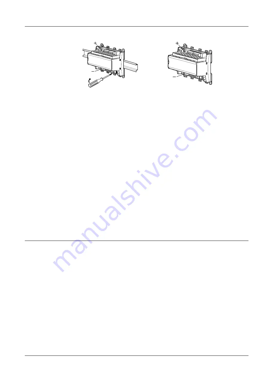
Rail mounting
The housing base is designed for snap-
mounting on DIN rails, type EN50022-
35x7.5 (can be released with a
screwdriver)
Surface mounting
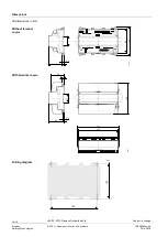
There are four drill holes for screw
mounting (see “Dimensions” for drilling
diagram). The housing base is fitted
with raised supports.
Screws: Max. diameter 3.5 mm
When mounting note the following:
•
Ensure adequate air circulation to dissipate heat generated during operation.
•
Easy access is required for service personnel.
•
Local installation regulations must be observed.
The mounting instructions and a drilling template are printed on the controller
packaging.
•
Avoid bends and constrictions when connecting the tubing
•
Connect the “+” connection to the higher pressure side and the “–“ connection to the
lower pressure side.
•
The recommended tube length is in the range 700 mm … 2 000 mm
•
When using an air filter, install it on the high pressure side (“+”), with the air flowing
through the filter in the correct direction.
•
Use an air filter to prevent the accumulation of dirt particle deposits on the sensor
element, especially when the extract air is contaminated (see technical data).
Commissioning
The RXC32 controller is commissioned with the RXT10 commissioning and service
tool. This is connected to the L
ON
W
ORKS
® bus via a tool socket (on the controller or
room unit).
The commissioning procedure for the entire Desigo RXC range is described in detail in
the RXT10 user manual, document CM110669.
The labeling fields “Appl.” and “Loc.” on the controller are used to indicate the
application actually loaded and the location of the controller, either in writing or by use
of printed adhesive labels (see “Label” under “Mechanical design”).
Connection, flow sensor
Labeling

