Removal from Switchgear
Prior to performing any inspection or maintenance checks
or tests, the circuit breaker must be removed from the
switchgear. The Installation and Initial Functional Tests
section describes the removal procedure in detail. Princi-
pal steps are repeated here for information and guidance,
but without the details of the preceding section.
Note: The Racking Mechanism is adjusted for proper
operation and should not be disturbed unless it be-
comes possible to close the breaker during a racking
operation.
It may be possible that interlocked blocking members
are not positioned properly, which should be corrected
as follows:
Remove the lower front mechanism cover plate and
with the circuit breaker closed, make adjustment by
regulating the length of connecting rod (Figure 2).
1. The first step is to de-energize the circuit breaker. De-
pressing the Trip pushbutton opens the breaker prior to
removal from the switchgear (Refer to Circuit Breaker
Operator / Manual SG-9918).
2. The second step in the removal procedure is to de-en-
ergize control power to the circuit breaker. Open the
control power disconnect device.
3. Rack the breaker to the “DISCONNECT” position.
4. Perform the spring discharge check. This is done by
first depressing the red Trip pushbutton. Second, de-
press the back Close pushbutton. Third, depress the
red Trip pushbutton again, and observe the spring con-
dition indicator. It should read Discharge (Refer to Cir-
cuit Breaker Operator / Manual SGIM-9918).
5. Remove the breaker from the switchgear. Refer to the
preceding installation section of this manual for special
instructions and precautions regarding removal of a
breaker which is not at floor level.
Checks of the Primary Power Path
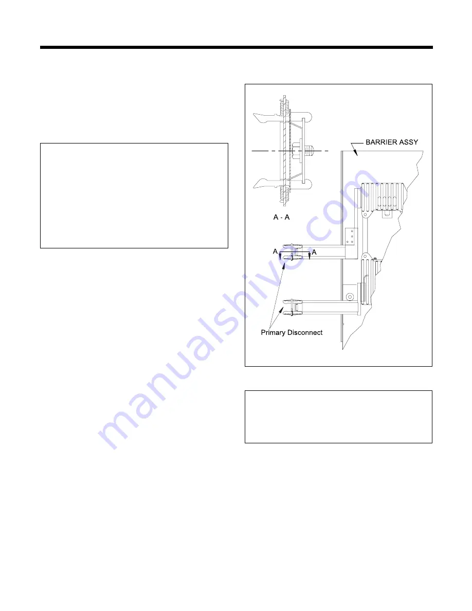
The primary power path consists of the three vacuum
interrupters, the three upper and the three lower primary
disconnects. These components are checked for
cleanliness and condition (Figure 4). The vacuum
interrupters are discussed in the Circuit breaker Operator
Manual SGIM-9918.
Maintenance
Figure 4. Primary Power Path
Inspection of Primary Disconnects and Cleanliness Check
Figure 4 is a side view of the DPR Circuit Breaker with the
insulating barriers removed to show the vacuum inter-
rupter, and the upper and lower primary disconnects.
All of these components must be clean and free of dirt or
any foreign objects. Use a dry lint-free cloth. For stubborn
dirt, use a clean cloth saturated with denatured alcohol.
The phase barriers are plates of glass polyester insulating
material and attached to the circuit breaker to provide suit-
able electrical insulation between the vacuum interrupter
primary circuits and the housing.
8
Note: Maximum Contact Resistance is read from pri-
mary bus stab to primary bus stab. A value of 13
micro-ohms should be added to the maximum con-
tact resistance specified in Circuit Breaker Operator
Manual SGIM-9918.


