Document No: IOM-002
Issue Date:
24/09/2020
Revision:
6
Page:
7 of 42
Unrestricted
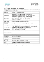
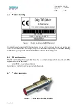
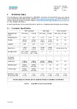
2.2
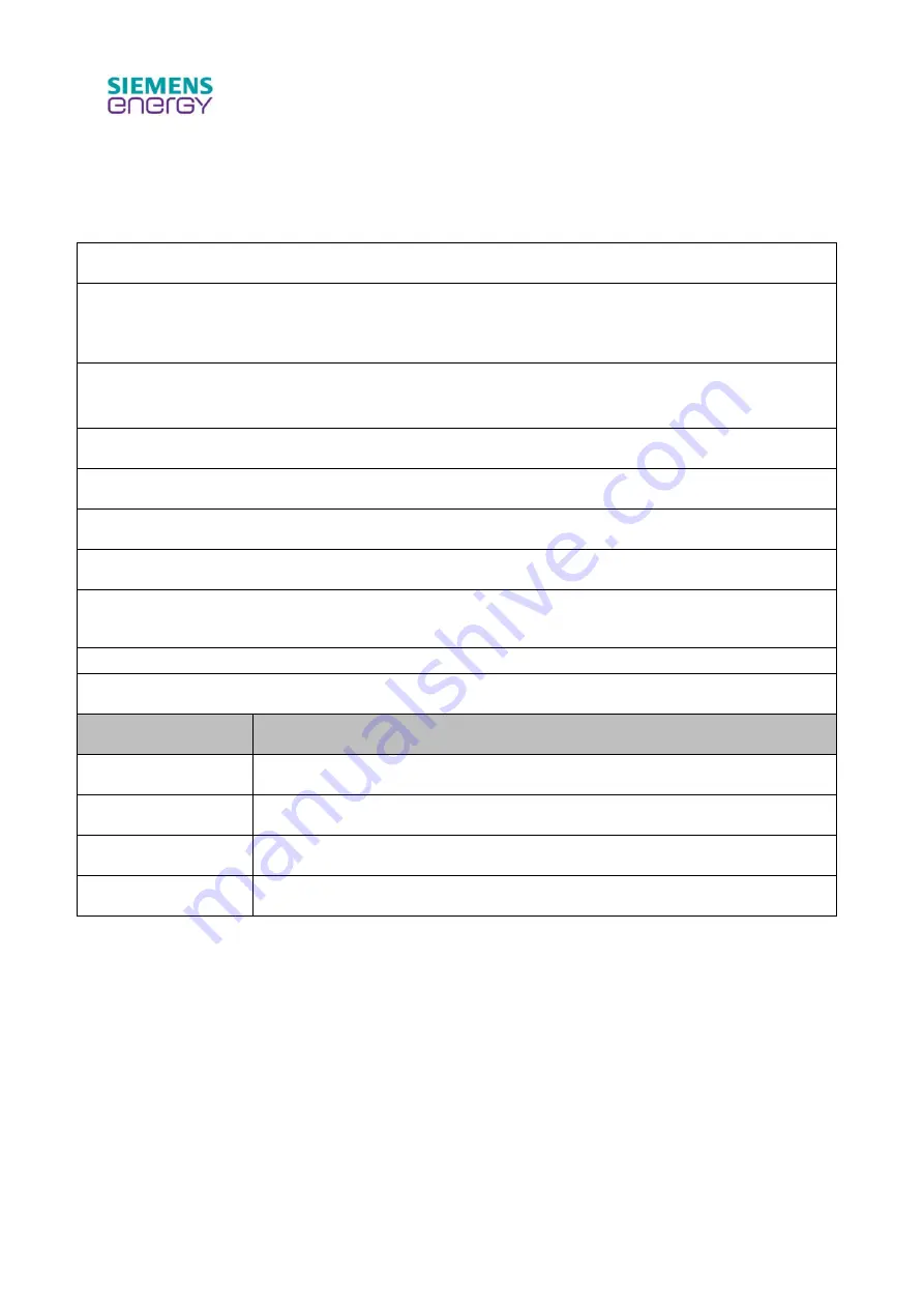
Product specification and certification
Basic specifications relating to all products covered by this manual are below in Table 3. Additional
specifications can be found in section 5.
Design Life:
30 years in subsea environment
Rated voltage
DigiTRON
+
1,000Vac pin-ground, 2,000Vac pin-pin
DigiTRON
e
Ethernet lines 50Vdc, other lines as DigiTRON
+
DigiTRON3 1,800Vac pin-ground, 2,000Vac pin-pin
Rated current
In water: 4-way 35-40A 7-way 22-32A 12-way 20-28A
In air: 4-way 18A 7-way 14A 12-way 11A
(Excludes ethernet lines)
Over-current
100A for 5 seconds, no more than 2 per hour
Rated number of
operations
1000 (750dry/250wet) mate / de-mate cycles (Power off)
Water depth
4,000 m (13,123ft)
Storage temperature
-40°C +70°C (-40°F +158°F) (upper limit is surface temperature of the
product and includes solar gain from bright sunlight)
Operational temp
Subsea: -5°C +60°C (+23°F +140°F)
In air: -20°C +50°C (-4°F +122°F)
Product Certification:
Standard
Description
EU Directive
2001/95/EC
General Product Safety
EU Directive
2014/35/EU
Low Voltage Directive
IEC 61984
Connectors - Safety requirements and tests
API-17F
Standard for Subsea Production Control Systems
Note: Self-certified via in-house testing.
Table 3
DigiTRON product specification and certification