


Document No: IOM-002
Issue Date:
24/09/2020
Revision:
6
Page:
27 of 42
Unrestricted
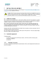
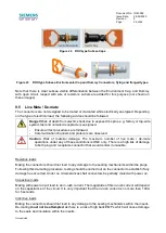
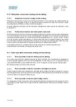
Figure 11
Typical bulkhead ROV connectors
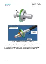
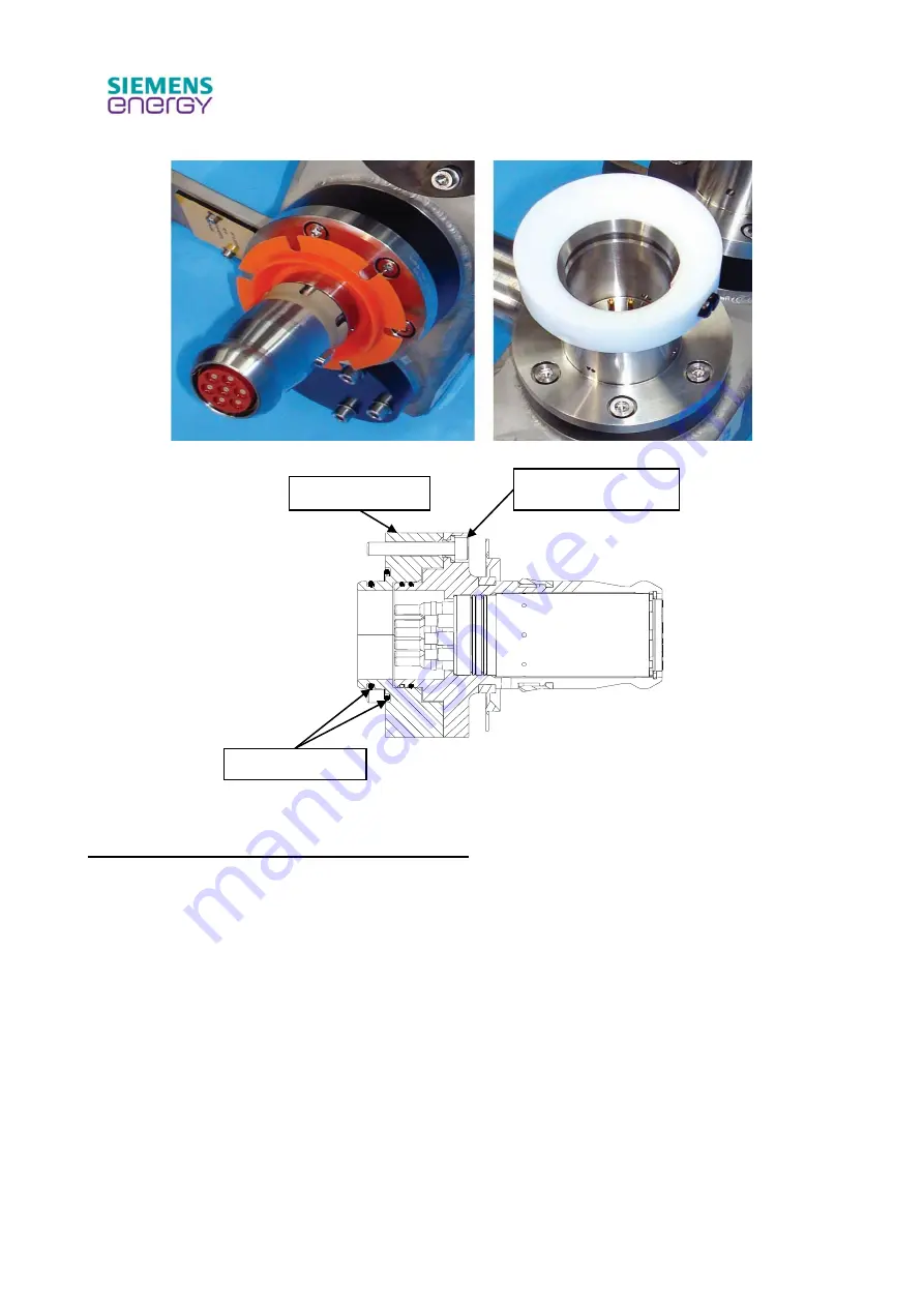
Figure 12
ROV bulkhead connector sectional view
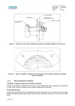
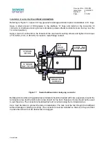
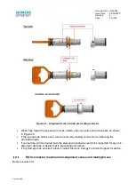
Installation of compliant flange mounted connector
Refer to Figure 13 for a typical flange-mounted ROV connector, and Figure 14 for installation
diagram.
Remove M6 mounting screws and orientation disc, pass the front of the connector through the
interface, install 4 off M6 mounting screws and orientation disc, secure screws with a spot of Loctite
243 on the threads and torque to 10-12 Nm (7.38
– 8.85 lbf.ft).:
Acetal flange
Install ‘O’ rings
Mounting screws


