background image

Direct-On-Line and Automatic Star – Delta Starter

Our new series of DOL and ASD starters complies to latest 
standard IS/IEC 60947-4-1

Operating Instructions

Selection:

•  Refer Table 1 for recommended 

selection of DOL Starters and 
Table 2 for ASD Starters.

•  DOL and ASD Starters are 

supplied without relays. Relays 
are to be fitted at site.

•  Select the suitable range of 

relay as per recommendation 
given in Table 1 and 2.

•  Select back-up fuse rating 

for different starters from 
the selection tables. The 
recommendation of the fuses 
and fuse switches is according 
to Type-2 co-ordination as per 
IS/IEC 60947-4-1.

Inspection:

•  Remove the housing cover.
•  Check the coil voltages so that, 

the coil voltage corresponds to 
actual supply voltage.

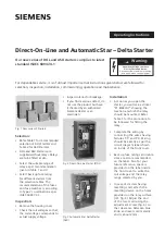
Fig. 2 Direct-On-Line Starter (DOL)

Fig. 3 Automatic Star Delta Starter 
(ASD)

•  Inspect interior for breakage.
•  If you find a serious defect, do 

not use the product but have 
it checked by an authorized 
Siemens dealer or an 
electrician.

Installation:

•  As soon as you open the 

starter, you will see a sticker 
“K1 BIRELAY” showing the 
location at which the relay 
should be mounted. Refer 
Table 5 for the procedure to 
be followed for fitting the 
relay.

•  Complete the wiring by 

connecting the wires having 
ferrules ‘95’ and ‘96’. Wiring 
should be exactly as per the 
circuit diagram label shown 
on inside of the front cover. 

•  Back up fuse ratings and cable 

sizes are also recommended 
on the label. Also for your 
future reference, space is 
provided on the label inside 
the front cover to write the 
coil voltage and the relay 
range selected by you.

•  In case of starters having 

resetting cord, attach the 
resetting device on the holes 
provided on the relay surface. 
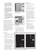
(ref. fig. 4) Adjust the end 
of the reset cord using the 
adjustment screw (fig. 4) so 
that clearance between blue 
knob and reset cord metallic 
end is about 2mm. 

Fig. 1 New series of Starters

For dependable service, it is of utmost importance that instructions given below are followed for 
selection, inspection, installation, commissioning, operation and maintenance.

s

Hazardous Voltage can cause 

Electric Shock and burns. 

Disconnect Power before proceeding 

with any work on this equipment

  Warning:

Summary of Contents for DOL Series

Page 1: ...on as you open the starter you will see a sticker K1 BIRELAY showing the location at which the relay should be mounted Refer Table 5 for the procedure to be followed for fitting the relay Complete the wiring by connecting the wires having ferrules 95 and 96 Wiring should be exactly as per the circuit diagram label shown on inside of the front cover Back up fuse ratings and cable sizes are also rec...

Page 2: ...rrent indicated when motor hum reaches a steady pitch c Stop the motor Set timer to this measured value by rotating the dial shown in fig 7 Overload relay setting a For closer protection set the overload relay to actual line current DOL or actual phase current ASD as measured by an Ammeter In the absence of an Ammeter use procedure as given below a Start the motor and let it run for an hour Then g...

Page 3: ...s tripped due to overload In this case you can restart the motor only if you reset it In case you want the starter to be in Self Reset mode the blue knob on relay fig 9 is to be pressed and rotated in anticlockwise direction so that it comes in position A and its edge Fig 8 Starter front view Fig 9 Relay front view Fig 10 Operating characteristics of 3US 5 6 relays Maintenance Keep the interior du...

Page 4: ...2 0A 3TS3511 0A 3TS3511 0A 3US56 00 2C8K 16 25 3KL815 50 16 10 30 40 53 30 6 3TE7494 2A 3TS3522 0A 3TS3511 0A 3TS3511 0A 3US56 00 2D8K 20 32 3KL815 63 16 10 37 50 65 37 5 3TE7495 2A 3TS3622 0A 3TS3511 0A 3TS3611 0A 3US56 00 2R8K 32 40 3KL821 80 16 10 45 60 78 45 ASD 3 3TE7496 2A 3TS4722 0A 3TS3522 0A 3TS4722 0A 3US58 00 2F8K 32 50 3KL821 100 35 16 55 75 96 55 4 3TE7497 2A 3TS4822 0A 3TS3522 0A 3TS...

Page 5: ...ing 3TW7498 2A 3 Loosen the screws of accessory for independent mounting ASD 3 3TE7497 2A 4 Put the relay terminals below the pin type lugs of the cable terminations 5 Hold the relay the way it is shown in the Operating Instructions of terminal carrier and engage the relay hook in the slot of the terminal carrier 6 When the relay edge is flush with terminal carrier edge clamp the relay with termi ...

Page 6: ...DOL 1 2 3TW7493 2A 3TW7494 2A 3TW7495 2A DOL 3 3TW7496 2A 3TW7497 2A 3TW7498 2A DOL 6 3TW7499 2A 3TW7590 2A s Fig 11 Dimensional Details 6 ...

Page 7: ...ASD 2 3TE7493 2A 3TE7494 2A 3TE7495 2A ASD 3 3TE7496 2A 3TE7497 2A 7 ...

Page 8: ... recycling through authorised dealer Because of the long lifetime of Siemens products the disposal guidelines may be replaced by other national regulations when taking the product out of service The local customer care service is available at any time to answer disposal related questions Siemens Products are environment friendly which predominantly consist of recyclable materials For disposal we r...

Reviews: