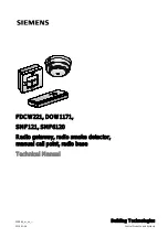
background image

FDCW221, DOW1171,
SMF121, SMF6120
Radio gateway, radio smoke detector,

manual call point, radio base

Technical Manual

009865_m_en_--

Building Technologies

2015-11-06

Control Products and Systems

Summary of Contents for DOW1171

Page 1: ...FDCW221 DOW1171 SMF121 SMF6120 Radio gateway radio smoke detector manual call point radio base Technical Manual 009865_m_en_ Building Technologies 2015 11 06 Control Products and Systems ...

Page 2: ... communication thereof to others without express authorization are prohibited Offenders will be held liable for payment of damages All rights created by patent grant or registration of a utility model or design patent are reserved Issued by Siemens Switzerland Ltd Building Technologies Division International Headquarters Gubelstrasse 22 CH 6301 Zug Tel 41 41 724 2424 www siemens com buildingtechno...

Page 3: ...171 24 3 2 1 Parameter sets for the radio smoke detector DOW1171 26 3 2 2 Scope of delivery 26 3 3 Structure of the manual call point SMF121 and radio base SMF6120 27 3 3 1 Scope of delivery 27 3 4 Product version ES 28 3 5 Details for ordering 29 3 6 RadioSpy 29 3 7 Accessories for the FDCW221 radio gateway 30 3 7 1 9 V lithium manganese dioxide battery 30 3 7 2 Micro terminal DBZ1190 AA 30 3 7 3...

Page 4: ...SMF6120 41 3 10 7 Power supply 42 4 Planning 43 4 1 Compatibility 43 4 2 Usage conditions 44 4 2 1 Environmental influences 44 4 3 Transmission field 45 4 4 Defining the place of mounting 47 4 5 Radio test set DZW1171 47 5 Mounting Installation 48 5 1 Installing and connecting the radio gateway FDCW221 48 5 2 Installing the radio smoke detector DOW1171 50 5 3 Installing the radio base SMF6120 and ...

Page 5: ...dying faults 70 7 7 Replace radio gateway 71 7 8 Replacing radio detectors 71 7 9 Replacing the glass plate on the manual call point SMF121 72 7 10 Updating the firmware of radio gateway FDCW221 73 8 Specifications 74 8 1 Technical data for the radio gateway FDCW221 74 8 2 Technical data for radio smoke detector DOW1171 76 8 3 Technical data for manual call point SMF121 and radio base SMF6120 77 8...

Page 6: ...Building Technologies 009865_m_en_ Fire Safety 2015 11 06 6 82 ...

Page 7: ...d the training courses for Product Managers Project Manager Coordinates the deployment of all persons and resources involved in the project according to schedule Provides the information required to run the project Has obtained suitable specialist training for the function and for the products Has attended the training courses for Project Managers Project engineer Sets parameters for product depen...

Page 8: ...f international standard ISO 8601 format YYYY MM DD Conventions for text marking Markups Special markups are shown in this document as follows Requirement for a behavior instruction 1 2 Behavior instruction with at least two operation sequences Version option or detailed information for a behavior instruction Intermediate result of a behavior instruction End result of a behavior instruction Number...

Page 9: ...USB Adapter FDUZ221 010087 Data sheet Radio fire detection system FDCW221 DOW1171 SMF6120 SMF121 A6V10200368 Installation Radio base SMF6120 Manual call point SMF121 A6V10217915 Installation RadioSpy A6V10229812 User Manual RadioSpy A6V10336734 Installation Radio gateway FDCW221 A6V10336739 Installation Radio smoke detector Base DOW1171 DBW1171 1 2 Download center You can download various types of...

Page 10: ...ter FDUZ221 MCL USB adapter Protocol converter from USB to MC Link Radio detector Devices which can communicate with the radio gateway using radio Radio cell Radio range i e range of a gateway Gateway Network bridge which links two different systems or networks LED Light emitting diode MC link Maintenance and commissioning link PC Personal computer RadioSpy Test unit for observing monitoring and c...

Page 11: ...hat the SMF6120 may only be used as a replacement device in existing fire detection installations installed prior to 2011 04 01 h 2011 08 Editorial changes made difference between FS20 FC20 revised number of batteries for SMF6120 and DOW1171 corrected document numbers of mounting instructions for FDCW221 and DOW1171 DBW1171 adapted new standard VdS approvals and CPD numbers for FDCW221 and DOW1171...

Page 12: ... The table below shows the published language versions with the corresponding modification index Modification index en_ de_ fr_ it_ es_ m X X X X X l X X X X X k X j X i X X X X X h X X X X X g X f X X X X X e X d X X c X X b X X X X X a X X X X X X published no publication with this modification index ...

Page 13: ...dangers the type of danger or possible consequences measures and prohibitions examples of which are shown in the following table General danger Explosive atmosphere Voltage electric shock Laser light Battery Heat Signal word The signal word classifies the danger as defined in the following table Signal word Danger level DANGER DANGER identifies a dangerous situation which will result directly in d...

Page 14: ...is shown as follows WARNING Nature and origin of the danger Consequences if the danger occurs Measures prohibitions for danger avoidance How possible damage to property is presented Information about possible damage to property is shown as follows NOTICE Nature and origin of the danger Consequences if the danger occurs Measures prohibitions for danger avoidance ...

Page 15: ...ordance with the electrotechnical regulations Wherever possible disconnect products from the power supply when carrying out commissioning maintenance or repair work on them Lock volt free areas to prevent them being switched back on again by mistake Label the connection terminals with external external voltage using a DANGER External voltage sign Route mains connections to products separately and ...

Page 16: ...ults malfunctioning and safety risks Written confirmation must be obtained from Siemens and the corresponding safety bodies for modifications or additions Modules and spare parts Components and spare parts must comply with the technical specifications defined by Siemens Only use products specified or recommended by Siemens Only use fuses with the specified fuse characteristics Wrong battery types ...

Page 17: ...jury and damage to property in the event of a fire Read the Release Notes before you plan and or configure a fire detection installation Read the Release Notes before you carry out a firmware update to a fire detection installation NOTICE Incorrect planning and or configuration Important standards and specifications are not satisfied Fire detection installation is not accepted for commissioning Ad...

Page 18: ...detectors logged onto it forms a radio cell The following diagram shows how the radio gateway is integrated in the fire detection via the FDnet Radio gateway on FDnet with radio detectors Features of the radio gateway FDCW221 Compatible with the FDnet compatible fire detection systems FS20 AlgoRex and Sigmasys Simultaneous operation of wired fire detectors on FDnet and wireless radio detectors on ...

Page 19: ...ion battery only needs replacing every 5 years Separate monitoring of each individual battery Even when a battery fails detector operation is still guaranteed for up to 30 days Built in alarm indicator Mounting with detector base DBW1171 accessories Features of the manual call point SMF121 and radio base SMF6120 Radio module is integrated in the radio base SMF6120 Radio base supply via two 3 6 V l...

Page 20: ... 82 Building Technologies 009865_m_en_ Fire Safety 2015 11 06 3 1 Structure of the radio gateway FDCW221 3 1 1 Overview Overall view of radio gateway 1 LED red green 4 Magnet movement for Reed contact 2 Housing cover 5 Unlocking for housing cover 3 Back box 1 2 3 5 4 ...

Page 21: ... of radio gateway 1 9 V battery with clip 6 LINE spring clips for the FDnet detector line 2 Battery cable connection 7 Brackets for cable strain relief using cable ties 3 MC link connection 8 SHIELD shield connection terminal blocks for detector line cables 4 Button for settings 9 Reed contact 5 Radio module SPU60xx See also 2 Connections 22 2 3 4 5 6 7 7 8 9 1 ...

Page 22: ...o used to update the radio gateway firmware The MCL USB adapter FDUZ221 is used to lead the firmware from the PC to the radio gateway You will find a description of firmware update in chapter Updating the firmware of radio gateway FDCW221 73 For details see document 009854 3 1 4 Radio transmission The radio module SPU60xx consists of a printed circuit board with two integrated aerials The radio mo...

Page 23: ...ersion is displayed as a fault within 300 s like other communication faults 3 1 5 Reed contact and button The Reed contact is an extra operating element which can be used to perform some of the functions of the button when the housing cover is closed Generally when commissioning the Reed contact can also be activated with a magnet rather than the button Activation of the Reed contact then equates ...

Page 24: ...t principle An infrared LED sends short intense light pulses to the scattering volume The orifices shield the light receiver from direct rays of light and reflexes Penetrating smoke particles scatter the light on the light receiver The signal of the light receiver is evaluated by the electronics Algorithms evaluate the smoke density and the probabilities of alarms are forwarded by the microprocess...

Page 25: ...ilding Technologies 009865_m_en_ Fire Safety 2015 11 06 Battery compartment and log on button on the DOW1171 1 Battery compartment for two 9 V lithium manganese dioxide batteries 2 New log on button See also 2 DBW1171 base 32 2 Structure of the radio smoke detector DOW1171 24 2 1 ...

Page 26: ...nt The table below contains lists of possible parameter sets and the average response times using test gas Parameter set no Parameter set name Average response time using test gas s 1 Default No verification Test applications not critical for deception 15 2 Short verification time 60 3 Average verification time 85 4 Maximum verification time 105 5 Maximum verification time also with strong filteri...

Page 27: ...ogether with the radio base SMF6120 The radio electronics are integrated with the two aerials in the radio base SMF6120 The radio base is battery operated and is supplied by two 3 6 V lithium batteries Figure 2 View inside radio base SMF6120 1 3 6 V lithium batteries 3 3 1 Scope of delivery The manual call point SMF121 and the radio base SMF6120 must be ordered separately Batteries are not include...

Page 28: ...ion on the packaging label Details of the product version can be found directly on the packaging label in the barcode Example of a packaging label with details of the product version Product version on the product label and the type plate Details of the product version can be found after the device order number Example of a product label with details of the product version Depending on the product...

Page 29: ...217 C1218 W100 Neutral manual call point SMF6120 S24218 F72 A1 Radio base for SMF121 The SMF6120 radio base may only be used as a replacement device in fire detection installations that were installed prior to April 1 2011 3 6 RadioSpy RadioSpy is an optional tool for installing radio cells and analysis in the event of problems The following modules form part of RadioSpy RadioSpy software installa...

Page 30: ...or T branches of additional cabling e g for detector heating units sounder base external alarm indicators etc For wire diameters of 0 28 0 5 mm2 4 pin Order no BPZ 4677080001 3 7 3 Connection terminal DBZ1190 AB Auxiliary terminal for connecting cables For T branches of additional cabling e g for cable shielding detector heating units sounder base external alarm indicators etc For wire diameters o...

Page 31: ...s Two part test unit For details see document 004446 Order no BPZ 5762200001 See also 2 Radio test set DZW1171 47 3 7 6 RadioSpy To assist with installing radio cells and analysis in the event of problems Components Compatible with For details see A6V10229812 document Order no S24218 F65 A1 3 7 7 Cable ties 2 4 x 137 For strain relief on the connection wires or generally for attachment Made from p...

Page 32: ...For supplying radio detectors radio gateways and service devices with power EVE lithium manganese dioxide type CR9V P S Li MnO2 9 V 1 2 Ah battery with pin cover Compatible with Order no A5Q00004142 3 8 3 DBZ1190 detector locking device For protection against theft Compatible with Order no BPZ 4585260001 3 8 4 Base attachment surface mounted humid DBZ1192 For mounting in humid or wet environments ...

Page 33: ...009865_m_en_ Fire Safety 2015 11 06 3 8 5 Protective cage DBZ1194 To protect the devices against mechanical damage Can only be used in conjunction with the following accessories Order no BPZ 4677110001 3 8 6 Designation plate DBZ1193A To identify the location Compatible with Order no BPZ 4864330001 ...

Page 34: ...tery For supplying radio detectors with power TADIRAN SL 760 lithium battery 3 6 V 2 2 Ah Battery with connection cables and plugs Compatible with Order no V24069 Z112 A1 3 9 2 Key For opening doors on manual call points Compatible with Order no S24217 G34 A1 3 9 3 Glass insert For alarm activation and protection against soiling Compatible with Order no S24217 G41 A1 See also 2 Replacing the glass...

Page 35: ...no radio cell overlapping the maximum address connection factor for the FDnet detector line limits the number of devices connected radio gateways detectors A maximum of 30 radio detectors can be connected to a radio gateway Each radio detector has its own address The radio gateway itself has two addresses The radio gateway may only be operated on a loop in the FDnet Since the radio gateway and con...

Page 36: ...18 Display on the test device Meaning Measures no deviation Normal no fault is present Radio gateway is fully functional None advice excha 1 Replacement recommended Radio gateway is still functional in spite of the battery voltage being too low FDCW221 Replace battery needed excha 1 Replacement necessary Radio gateway is only being supplied with power via the detector line FDCW221 Replace or inser...

Page 37: ...21 has the following operation modes Normal operation Start up operation Configuration operation 3 10 3 1 Normal operation The radio gateway is in intended operation All of the radio detectors within the radio cell are monitored 3 10 3 2 Start up operation As soon as the radio gateway is energized it goes into start up operation In start up operation the radio gateway checks whether radio detector...

Page 38: ...FDCL221 line separator In terms of topology the radio detectors logged onto the radio gateway are in a stub The stub branches off on the FDnet detector line between the FDCW221 and the integrated line separator FDCL221 of the radio gateway see figure below Figure 3 Topology of radio gateway on FDnet Gateway Radio gateway housing M1 Radio detector 1 on stub FDnet FDnet spring clips on radio gateway...

Page 39: ...D in the cover The flash sequences are displayed in parallel on the two green LEDs or the two red LEDs The flash sequences of the amber LED inside the radio gateway cannot be displayed by the LED in the housing cover The amber LED only displays flash sequences if radio detectors are to be removed LEDs for status display 1 Internal LED amber H3 3 Internal LED red H4 2 Internal LED green H2 4 LED in...

Page 40: ...lowly Off Off No free channel found Flashes rapidly Flashes rapidly Off Log other radio detectors on to gateway Off Flashes quickly for 3 s Off Radio detector logged on to gateway Flashes rapidly Off Off Radio detector could not be logged on to gateway 30 radio detectors already logged on Off Off Flashes slowly Radio gateway ready to log off a radio detector Off Flashes slowly Flashes slowly A rad...

Page 41: ...on 3x 2 s Re log on 1x long 2 s System search Attempt to establish a radio link to a radio gateway 4x s1 Field strength following successful radio detector log on to radio gateway High receive field strength 3x s1 Field strength following successful radio detector log on to radio gateway Average receive field strength 2x s Field strength following successful radio detector log on to radio gateway ...

Page 42: ...nel Brief open lines 5 hours on the detector line can be bridged by the 9 V lithium manganese dioxide batteries DOW1171 radio smoke detector Power is supplied to the power supply via two 9 V lithium manganese dioxide batteries Manual call point SMF121 and radio base SMF6120 Power is supplied to the manual call point and the radio base via two 3 6 V lithium batteries The battery compartment is loca...

Page 43: ...cations etc The radio gateway may only be operated on a loop in the FDnet Since the radio gateway and connected radio detectors form a stub this configuration must never be used in stub operations If it is an impermissible stub on stub topology will result See also 2 Radio test set DZW1171 47 2 Defining the place of mounting 47 2 Transmission field 45 4 1 Compatibility Compatible with control pane...

Page 44: ... distance between the radio gateway and radio detector must be noted max 40 m depending on field strength measurement The building construction will have a major impact on the radio range Steel Concrete Thick or damp walls Transmission field damping and reflection Doors must be closed when measuring the field strength Mirrors in the room will have a negative impact on damping Limitations The follo...

Page 45: ...m values Distance 40 m damping 90 dB Table for converting to linear values Damping factor 1 4 10 50 100 1000 Damping dB 0 6 10 17 20 30 The transmission field in the building is affected by walls and obstacles These constructions walls ceilings etc must be analyzed in detail to obtain a statement on damping Radio damping when passing through obstacles The approximate values listed in the table sho...

Page 46: ... wall 40 dB Sample calculation A radio gateway is fitted under an armored concrete ceiling The partition walls are made from concrete Radio gateway with radio links A B C Path A 5 m Free space armored concrete ceiling 40 30 70 dB Path B 15 m Free space armored concrete ceiling concrete wall 67 30 6 103 dB Path C 10 m Free space concrete wall 57 6 63 dB Result Paths A and C can be used The radio de...

Page 47: ...eway You can then also fit the radio gateways at a greater distance This will also ensure that temporary changes to the transmission fields do not result in malfunctions as a result of the same basic channels being occupied several times over Measure the distances between the radio gateway and radio detector on the building plan in advance and calculate the damping For reliable planning you will h...

Page 48: ...0 AB for cables with a diameter of 1 5 2 5 mm2 Obtain a corresponding terminal from the customer for even larger cross sections The terminal can be positioned inside the housing Fit the radio gateway such that it is easily accessible for battery changes and for the following operating elements MC link plug connection button and Reed contact Ensure suitable position so that the LEDs are visible Not...

Page 49: ...k out openings in supporting surface of back box Surface mounted cable entry Break open openings in face end of back box 5 Guide cables through back box and use two screws max diameter 4 3 mm to fit back box on a level surface 6 Prepare the detector line wires such that they can be connected to the LINE spring clip later on 7 Connect negative and positive poles of the detector line with a micro te...

Page 50: ... the base such that the alarm indicator of the radio smoke detector DOW1171 is clearly visible from the investigation route 2 Install the base with two screws on a level surface Note the minimum distances to be complied with 3 Install a designation plate DBZ1193A accessory if necessary 4 Install the radio smoke detector DOW1171 on the base DBW1171 Mounting location of the radio smoke detector 1 DO...

Page 51: ...oke detector DOW1171 is installed on the base DBW1171 1 Remove the radio smoke detector DOW1171 from the radio base DBW1171 2 WARNING Device does not work Only use the battery type intended for the device 3 Connect clip to 9 V lithium manganese dioxide battery contacts and insert battery in back box s battery compartment Repeat this step for the second battery 4 Install the radio smoke detector in...

Page 52: ...a detector locking device DBZ1190 accessory if necessary Installing the detector locking device DBZ1190 1 DBW1171 base 2 DBZ1190 detector locking device If you use the detector locking device DBZ1190 you can only unlock radio smoke detectors inserted in the base DBW1171 using a screwdriver See also 2 DBZ1190 detector locking device 32 2 9 V lithium manganese dioxide battery 30 2 1 ...

Page 53: ...manual call point SMF121 Installing the radio base SMF6120 w Ensure that the radio base SMF6120 is connected to the radio gateway FDCW221 from its intended location l Secure the radio base at a height of 1 3 1 6 m on a level surface using suitable screws Use the mounting openings 1 Note the word TOP on the radio base housing Mounting openings in the radio base SMF6120 1 Mounting openings 1 1 ...

Page 54: ...es not work if the terminal assignment deviates Use only terminals b and b 5 Clip one connection cable each to terminals b and b in the terminal strip 6 Secure the manual call point to the radio base using the screws supplied 7 Stick on the ATTENTION sign If the feed lines are interrupted Alarm triggered is displayed on the inside of the door of the manual call point 8 Close the door of the manual...

Page 55: ...radio base SMF6120 1 Open the door of the manual call point using a suitable key 2 Remove the fixing screws in the manual call point and lift the manual call point off the radio base 3 Press the alarm button 2 4 WARNING Device does not work Only use the battery type intended for the device 5 Insert two 3 6 V lithium AA batteries into the radio base 6 Connect the batteries plug connections to the t...

Page 56: ...ling the radio base SMF6120 and manual call point SMF121 5 56 82 Building Technologies 009865_m_en_ Fire Safety 2015 11 06 View inside manual call point SMF121 1 Reset slider 2 Alarm button See also 2 3 6 V lithium battery 34 1 2 ...

Page 57: ...ontact can also be activated with a magnet rather than using the button Starting up radio cell A radio cell must be commissioned as described below following some basic rules 1 Start up radio gateway 2 Log radio detector on to radio gateway 3 Start up radio gateway on detector line See also 2 RadioSpy 29 2 Status display on the radio gateway FDCW221 39 2 Starting up the radio gateway 58 2 Logging ...

Page 58: ...as a result of the same basic channels being occupied several times over Procedure w The FDnet detector line must be switched off w The radio gateway is in its delivery status w Several radio gateways must not be started up at the same time w There is a new battery ready for the radio gateway 1 Unlock the housing cover of the radio gateway on the face side using a pin 2 Remove the housing cover 3 ...

Page 59: ... Resetting DOW1171 to delivery status or Resetting SMF6120 to delivery status chapters 1 Insert batteries into the radio detector Press the alarm button on the SMF6120 too 2 Screw the radio smoke detector DOW1171 into the base and the manual call point SMF121 into the radio base SMF6120 3 Press the reset slider for the alarm button on the manual call point a The radio detector is automatically log...

Page 60: ... Starting up the radio gateway on the detector line Once all the radio detectors of a radio cell have been logged on to the radio gateway in battery mode the FDnet detector line can be started up Connection diagram for FDnet detector line Procedure 1 Connect the FDnet detector line cable to the LINE spring clips 2 Start the FDnet detector line up again You will find instructions on commissioning t...

Page 61: ... detects the radio detector to be removed with SMF6120 detection will take up to four minutes a Amber and green LEDs in radio gateway flash slowly in turn 3 Press the button in the radio gateway for more than three seconds a LEDs go out a Log off is confirmed a The radio detector is logged off and the radio gateway switches to normal operation the DOW1171 also signals correct logging off i e its s...

Page 62: ... line is switched off 1 Unlock the housing cover of the radio gateway on the face side using a pin 2 Remove the housing cover 3 Unplug the battery plug connection for at least 10 seconds 4 Then re insert the battery plug connection a Wait for green LED to flash quickly 5 Briefly press the button in the radio gateway while the green LED is flashing a The radio gateway is initialized and returns to ...

Page 63: ...leted Only reset the radio smoke detector to its delivery status if the existing configurations can be deleted Ensure that no gateway is in configuration mode during the reset process Exception The reset radio device should be logged back on to the gateway immediately Figure 4 Rear of radio smoke detector DOW1171 1 New log on button 3 Battery clips 2 9 V lithium batteries The New log on button 1 c...

Page 64: ...ug the clips back on to the two batteries and insert the batteries into the brackets a The status indicator flashes three times repeatedly 5 Press the New log on button until the status indicator only flashes once 6 Screw the radio smoke detector into the base and wait until the status indicator displays System search a The configuration data has been deleted from the radio smoke detector DOW1171 ...

Page 65: ...radio base to delivery status All existing configurations are deleted Only reset the radio smoke detector to its delivery status if the existing configurations can be deleted Ensure that no gateway is in configuration mode during the reset process Exception The reset radio device should be logged back on to the gateway immediately Figure 5 View inside manual call point SMF121 1 Reset slider 2 Alar...

Page 66: ...Press the alarm button on the manual call point SMF121 5 Plug both plugs of the battery connection cable back into of the printed circuit board in the radio base a The status indicator flashes three times repeatedly 6 Press the New log on button in the radio base until the status indicator only flashes once 7 Reset the alarm button using the reset slider on the manual call point SMF121 and wait un...

Page 67: ...teway is in normal operation and is being powered by the FDnet detector line without any interruptions w The new battery is ready to be inserted 1 Unlock the cover of the radio gateway on the face side using a pin 2 Pull off the cover of the radio gateway 3 Replace the battery 4 Snap the cover of the radio gateway back into the back box It may take up to 30 minutes for the battery fault message to...

Page 68: ...dio smoke detector per radio cell may be briefly without batteries Procedure w The FDnet detector line or detector zone is switched off w The radio gateway is in normal operation w The new 9 V batteries for the DOW1171 are ready for inserting 1 Unscrew the radio smoke detector DOW1171 from the base 2 Remove the old batteries from the DOW1171 3 Wait 10 seconds for the batteries to discharge 4 Inser...

Page 69: ...after another Only one manual call point per radio cell may be briefly without batteries Procedure w The FDnet detector line or detector zone is switched off w The radio gateway is in normal operation w The new 3 6 V lithium batteries for the SMF6120 are ready for inserting 1 Open the manual call point with radio base SMF6120 2 Remove the old batteries from the SMF6120 3 Wait 10 seconds for the ba...

Page 70: ... faults The following problems may arise A radio detector cannot be logged on in configuration operation There are already 30 radio detectors logged on to the radio gateway The radio gateway can still be put into configuration operation with the 31st radio detector but the radio detector cannot log on Remedy Use another radio gateway Control panel not correctly displaying the fire detection topolo...

Page 71: ...inutes until the data is fully synchronized 3 Switch the FDnet detector line back on 4 Select Accept replaced devices on the control panel Procedure without RadioSpy The radio gateway must be fully reconfigured after replacement See also 2 Starting up the radio gateway 58 7 8 Replacing radio detectors You will find points 2 and 4 listed below in relation to replacing a radio detector in the corres...

Page 72: ...l point SMF121 is installed on the radio base SMF6120 1 Open the door using a suitable key NOTICE Keep the key in a safe place 2 Remove the old glass pane 3 Push the retainer 1 to the right 4 Place the glass pane under the guide 2 and under the retainer 1 The glass pane is square shaped and can be inserted in any direction 5 Release the retainer 1 6 Close the door Figure 7 Replacing the glass plat...

Page 73: ... is carried out a The separators for the radio gateway FDCW221 are open 7 Remove the MC link cable from the radio gateway FDCW221 once the update routine is complete 8 Restart the detector line on the line tester FDUL221 a The separators for the radio gateway FDCW221 are closed 9 If necessary Update the firmware of additional radio gateways FDCW221 on this detector line see steps 4 to 8 10 After u...

Page 74: ... of compatibility Design Inherently short circuit proof Protected against polarity reversal Protected against overvoltage Line separator Line voltage Nominal DC 32 V Vnom Minimum DC 12 V Vmin Maximum DC 33 V Vmax Voltage at which the separator opens Minimum DC 7 5 V VSO min Maximum DC 10 5 V VSO max Permanent current when switches are closed Max 0 5 A IC max Switching current e g in the event of a...

Page 75: ...ector line Design Spring clips Cable cross section 0 2 1 5 mm2 MC link Design Plug connection Ambient conditions Operating temperature 10 55 C Storage temperature 30 65 C Air humidity 95 rel Protection category IEC 60529 IP40 Electromagnetic compatibility 1 MHz 2 GHz 30 V m Mechanical data Dimensions L x W x H 214 x 58 x 33 mm Weight not including battery 0 190 kg Material Polycarbonate PC Makrolo...

Page 76: ...ing aerials 2 aerial diversity Radio transmission Frequency range 868 870 MHz SRD band Short Range Device Channel grid 25 kHz Transmitting power 5 mW ERP Range In building Max 40 m Outdoors Max 200 m Battery Number of batteries 2 Voltage DC 9 V Type Block Li MnO2 ULTRALIFE U9VL J or EVE CR9V P S Capacitance 1200 mAh Service life 5 years Battery voltage monitored Yes Ambient conditions Operating te...

Page 77: ...stalled prior to April 1 2011 Radio Number of radio detectors per radio gateway Max 30 Sending receiving aerials 2 aerial diversity Radio transmission Frequency range 868 870 MHz SRD band Short Range Device Channel grid 25 kHz Transmitting power 5 mW ERP Range In building Max 40 m Outdoors Max 200 m Battery Number of batteries 2 Voltage DC 3 6 V Type TADIRAN SL 760 lithium Capacitance 2 2 Ah Servi...

Page 78: ...82 Building Technologies 009865_m_en_ Fire Safety 2015 11 06 8 4 Dimensions Radio gateway FDCW221 Radio smoke detector DOW1171 with base DBW1171 Manual call point SMF121 with radio base SMF6120 58 213 5 33 4 73 Ø 119 Ø 115 125 125 57 ...

Page 79: ...ures have been undertaken Use of reusable materials Use of halogen free plastics Electronic parts and synthetic materials can be separated Larger plastic parts are labeled according to ISO 11469 and ISO 1043 The plastics can be separated and recycled on this basis Electronic parts and batteries must not be disposed of with domestic waste Take electronic parts and batteries to local collection poin...

Page 80: ...nosis levels Radio gateway 36 Disposal 79 Distance Damping 45 Download center URL 9 E Environmental compatibility 79 Environmental influences 26 44 ES Product version 28 EU directives 74 76 77 F Field strength Link quality 59 Field strength measurements 47 Fire control panel failure Degraded mode operation 37 Firmware Update 22 73 Frequency range 22 I Impact Chemicals 44 Moisture 44 Temperature 44...

Page 81: ...9 Radio module SPU60xx 22 Radio smoke detector Parameter sets 26 Smoke sensitivity 26 Status indicator 41 Radio test set 43 RadioSpy Tool 29 Recycling 79 Reed contact Magnet 23 S Short circuit Line separator 38 Smoke sensitivity 26 Source language 8 Standards 75 76 77 Status indicator 41 Field strength 41 T Tool RadioSpy 29 Topology 38 Type plate Product version 28 ...

Page 82: ...ational Headquarters Gubelstrasse 22 CH 6301 Zug 41 41 724 24 24 www siemens com buildingtechnologies Siemens Switzerland Ltd 2007 Technical specifications and availability subject to change without notice Document ID 009865_m_en_ Manual FD20 Edition 2015 11 06 Register 5 ...

Reviews: