DEVICE PROGRAMMING UNIT USER’S MANUAL
|
CHAPTER 3
28
TESTING
CABLE P/N 555-133920
(5 ft. cable)
STACKING
BANANA
PLUG
GREEN
BANANA
JACK
RED
BANANA
JACK
BLACK
BANANA
JACK
PROGRAMMING
PLUG
TO WIRE OF
LINE 1
DEVICE LOOP
OF
TO WIRE OF
LINE 2
DEVICE LOOP
OF
TO EARTH
GROUND
CABLE P/N 555-133891
WITH ALIGATOR CLIPS
(3 ft. Cable)
BOTTOM
OF DPU
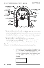
To Connect the DPU to Test for Device Communication:
• Insert the programming plug in one end of Cable P/N 555-133891 into the red and black
jacks in the cable compartment in the bottom of the DPU.
the other
• Make the connections described above to test for device communication.
• Insert the stacking banana plug of Cable P/N 555-133920 into the green jack in the
cable compartment in the bottom of the DPU.
• Connect the alligator clip on the other end of Cable P/N 555-133920 to Earth Ground.
• Attach the two alligator clip adaptors provided to the programming plug on
end
of cable P/N 555-133891. Connect one clip to the wire of Line 1 from the device loop to
be tested. Connect the other clip to the wire of Line 2 from the device loop to be tested.
To Connect the DPU to Test for Ground Faults:
Figure 3
Connecting The DPU To Test For Communication And Ground Faults
•
With the DPU displaying the Main Menu, press the
LOOP TEST button. Note that this is visible only if the
DPU is set to the FireFinder-XLS / FS-250 / FC20
(FC2025, FC2050, FC2005, FC922, FC924 or FC901)
system. The DPU will show a display similar to the
following:
GROUND FAULT = NO
INTEL. DEVICES = 121
<SUMMARY
<EXIT DETAIL>


