Wiring and interfaces
ECOFAST Motor Starters
GWA 4NEB 950 5221-12 DS 01
2-7
Deutsc
h
En
glish
2.3
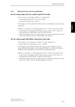
Motor terminal (Han 10E)
Notes
Danger
Ensure that the wiring is carried out carefully and correctly.
The temperature
sensor terminals must not be connected to 400 V AC.
Otherwise motor star-
ters may be destroyed. There is potentially
lethal danger!
For this reason, the motor line must be laid in such way that the cable cannot
get jammed or squashed!
Caution
Safe separation between 400 V AC and 24 V DC is only guaranteed on a motor
with safe separation of the temperature sensor circuit with respect to the stator
winding.
2.3.1
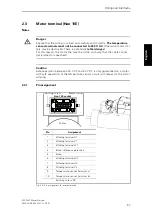
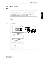
Pin assignment
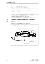
Fig. 2-4: Pin assignment
for motor terminal
10 9 8 7 6
5 4 3 2 1
Pin
Assignment
1
Winding terminal U1
2
Winding terminal V1
3
Winding terminal W1
4
Brake (reference potential)
5
Brake
6
Winding terminal W2
7
Winding terminal U2
8
Winding terminal V2
9
Temperature sensor (terminal a)
10
Temperature sensor (terminal b)
Earthing screw: PE
Han 10E socket
Earthing screw
Motor starter
Motor
Summary of Contents for Ecofast 3RK1 323-2AS54-1AA0
Page 1: ...Motor Starter Manual 03 2007 ecofast Totally Integrated Automation ...
Page 2: ......
Page 12: ...ECOFAST Motor Starters viii GWA 4NEB 950 5221 12 DS 01 ...
Page 40: ...Installation of Motor Starters ECOFAST Motor Starters 3 8 GWA 4NEB 950 5221 12 DS 01 ...
Page 58: ...Device functions ECOFAST Motor Starters 6 6 GWA 4NEB 950 5221 12 DS 01 ...
Page 74: ...ECOFAST Motor Starters GWA 4NEB 950 5221 12 DS 01 ...
Page 75: ......

