Copyright © Siemens AG 2016. All rights reserved
161
ERTEC 200P-2 Manual
Technical data subject to change
Version 1.0
2.3.5.3 AHB-Slave Interface
The AHB-slave interface supports the following features:
Supports AHB 2.0 lite protocol (No SPLIT, no RETRY)
Burst transactions are accepted at the AHB input side.
o
if the SDRAM controller is active, bursts of undefined length are split into
bursts of length 16.
o
if the asynchronous controller is active, any burst is split into single transfers
(exception of this rule: read access to Burst Flash ROM allows 16 beat
burst, read access to Page Mode ROM allows 16 beat burst).
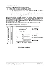
The EMC itself can be configured using the AHB slave interface
and contains an address code which divides the EMC address range of the AHB into 6
sub-ranges. The first sub-range is designed for 256 MByte SDRAM. The second range is
subdivided into 4 areas of 64 MByte each and is designed for the SRAM and other asyn-
chronous memory modules. The last range contains the internal EMC registers which
have an address range of 1 MByte.
The interface can be adapted to the RAM blocks used by the configuration registers.
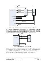
The diagram below shows address range allocation:
Figure 13: EMC, Address Space
A
H
B
a
d
d
r
e
s
s
s
p
a
c
e
e.
g. SDRAM
.
address sub
-
range #
1
:
configuration
#1
fix
: 256 MByte
s
u
b
- r
a
n
g
e
#
2
:
c
o
n
f i g
u
r a
t i o
n
#
2
EMC internal registers
e
.
g
. BURST Flash ROM
e
.g
. SRAM
A
d
d
r
e
s
s
D
e
c
o
d
e
r
max. 64 MByte
max. 64 MByte
max. 64 MByte
max. 64 MByte
1 MByte


